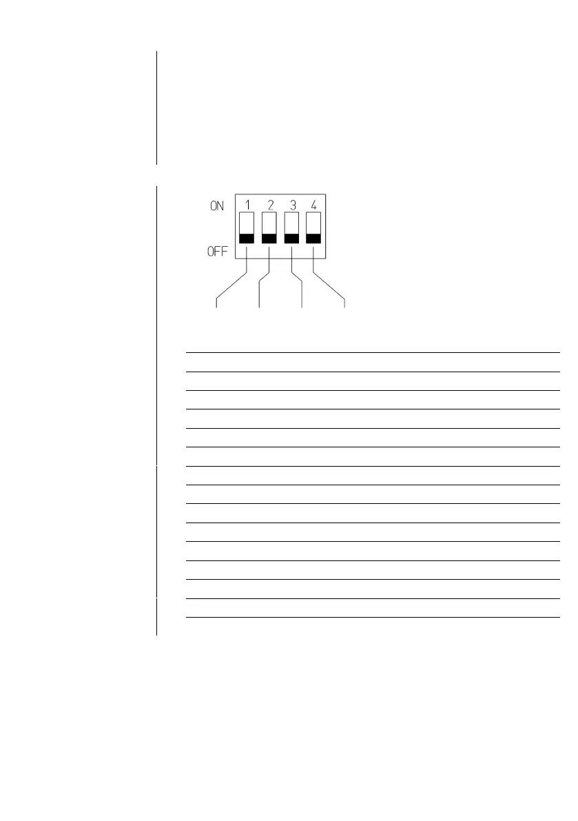
EasyManuals Logo

T+A E 1000 Series User Manual

T+A E 1000 Series
To Next Page IconTo Next Page
To Previous Page IconTo Previous Page
Page #19 background imageLoading...
Page #19 background image
19
Miniature switches 2are used to set the desired input capacitance for
the left (2L) and right (2R) channels. The information you need for this
will be included in the manufacturer’s specification for the pick-up system
you intend to use. Select the value which is closest to the manufacturer’s
stated figure. Note that the phono connecting lead also represents a
capacitance in the range 50 to 200 pF, depending on the manufacturer. It
is essential to set the same value for both channels. If you do not have
access to the manufacturer’s specification, a good starting point for input
capacitance is 120 pF. This is the factory default setting.
OFF
OFF
OFF
OFF
<
120 pF
OFF
OFF
OFF
ON
121 pF
...
140 pF
OFF
OFF
ON
OFF
141 pF
...
160 pF
OFF
OFF
ON
ON
161 pF
...
190 pF
OFF
ON
OFF
OFF
191 pF
...
220 pF
OFF
ON
OFF
ON
221 pF
...
240 pF
OFF
ON
ON
OFF
241 pF
...
260 pF
OFF
ON
ON
ON
261 pF
...
290 pF
ON
OFF
OFF
OFF
291 pF
...
340 pF
ON
OFF
OFF
ON
341 pF
...
360 pF
ON
OFF
ON
OFF
361 pF
...
380 pF
ON
OFF
ON
ON
381 pF
...
400 pF
ON
ON
OFF
OFF
401 pF
...
440 pF
ON
ON
OFF
ON
441 pF
...
460 pF
ON
ON
ON
OFF
461 pF
...
480 pF
ON
ON
ON
ON
481 pF
...
500 pF
Table 2

Questions and Answers:

Question and Answer IconNeed help?

Do you have a question about the T+A E 1000 Series and is the answer not in the manual?

T+A E 1000 Series Specifications

General IconGeneral
BrandT+A
ModelE 1000 Series
CategoryControl Unit
LanguageEnglish