www
.
T
r
a
il
F
X
.
c
om
Page 6 of 8 Rev 051918
8.
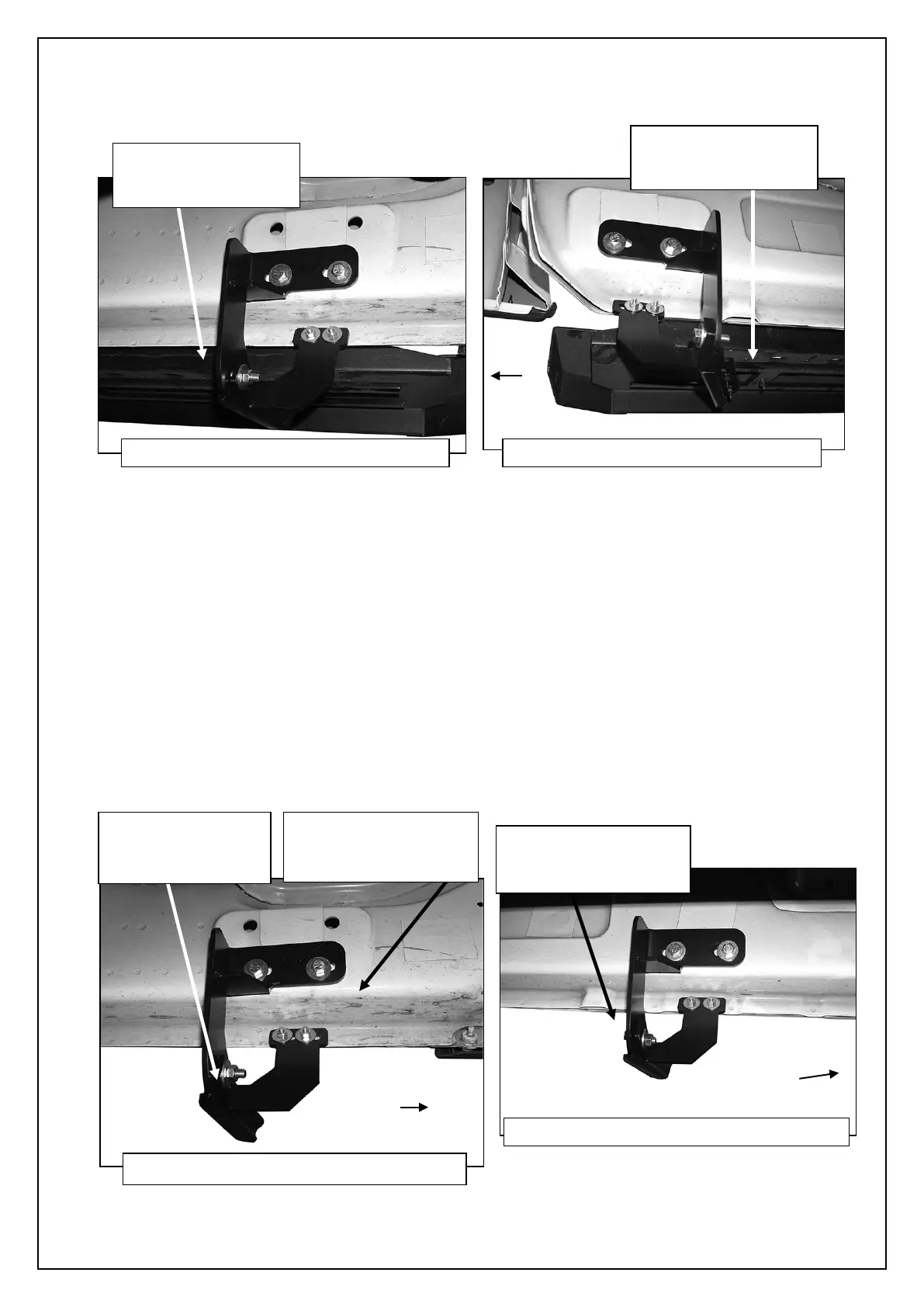
Attach the Running Board to the Brackets with (6) 6mm Flat Washers, (6) 6mm Lock Washers and (6) 6mm Hex Nuts, (Figures
19 & 20). NOTE: The Running Board is designed to fit close to the vehicle. It may be necessary to loosen the Bracket hardware
and tilt the Brackets downward to insert the Running Board between the Brackets and the body. Do not tighten hardware at this
time.
9. Properly level and adjust the Running Board and fully tighten all hardware.
2009-12 models requiring drilling for driver side Support Brackets:
a. Make sure the Running Board is level to the vehicle. Adjust and tighten all mounting hardware.
b. Line up the slots on the Support Brackets with the back of the pinch weld. Mark the location of the slots onto the pinch
weld.
c. Drill (2) 1/4” holes through the pinch weld for each Support Bracket. IMPORTANT: Do not drill too close to the bottom edge
of the pinch weld. Adjust the Brackets as necessary to move the slots up the body panel away from the edge. Drill the
holes toward the outside of the marked slots.
d. Attach each Support Bracket to pinch weld with (2) 6mm Hex Bolts, (4) 6mm Flat Washers and (2) 6mm Nylon Lock Nuts,
(Figures 12, 14, 17, 19 & 20). Check for level and fully tighten all hardware.
(Fig 19) Driver/left front Bracket assembly
(2) 6mm Lock Washers
(Fig 20) Driver/left rear Bracket assembly
(2) 6mm Lock Washers
(4) 6mm Flat Washers
(Fig 12) Driver side front Bracket assembly
(2) 8mm Flat Washers
8mm Nylon Lock Nut
(Fig 14) Driver/Left center Brackets installed
(2) 8mm Flat Washers
 Loading...