|nstaller's Guide
@
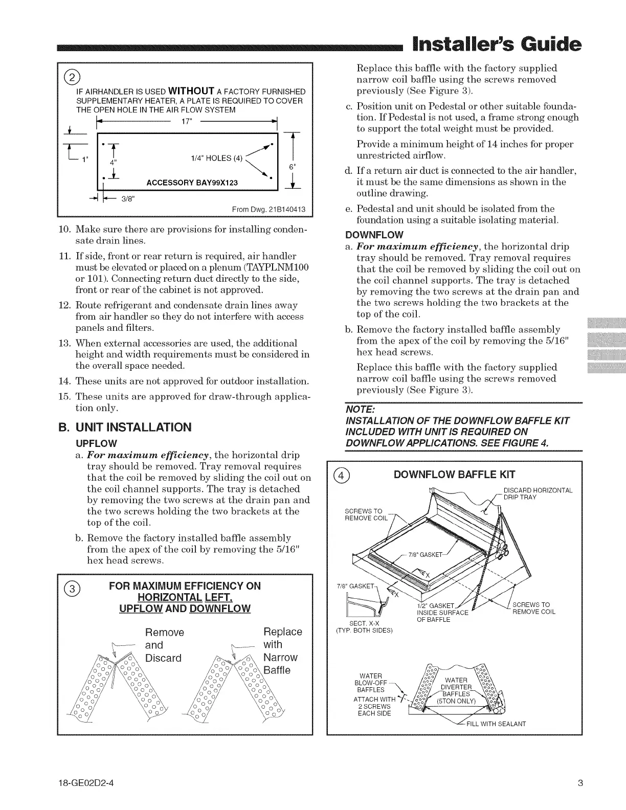
IF AIRHANDLER IS USED WITHOUT A FACTORY FURNISHED
SUPPLEMENTARY HEATER, A PLATE IS REQUIRED TO COVER
THE OPEN HOLE IN THE AIR FLOW SYSTEM
_L I"
I'T .±
_-- 3/8"
17" b]
1/4" HOLES (4) _o
ACCESSORY BAY99X123
From Dwg. 21 B140413
!0. Make sure there are provisions for installing conden-
sate drain lines.
!1. If side, front or rear return is required, air handler
must be elevated or placed on a plenum (TAYPLNM100
or 101). Connecting return duct directly to the side,
front or rear of the cabinet is not approved.
12. Route refrigerant and condensate drain lines away
from air handler so they do not interfere with access
panels and filters.
13. When external accessories are used, the additional
height and width requirements must be considered in
the overall space needed.
14. These units are not approved for outdoor installation.
15. These units are approved for draw-through applica-
tion only.
B. UNIT INSTALLATION
UPFLOW
a. For maximum efficiency, the horizontal drip
tray should be removed. Tray removal requires
that the coil be removed by sliding the coil out on
the coil channel supports. The tray is detached
by removing the two screws at the drain pan and
the two screws holding the two brackets at the
top of the coil.
b. Remove the factory installed baffle assembly
from the apex of the coil by removing the 5/16"
hex head screws.
®
FOR MAXIMUM EFFICIENCY ON
HORIZONTAL LEFT,
UPFLOW AND DOWNFLOW
Remove
and
Discard
Replace
with
Narrow
Baffle
C.
Replace this baffle with the factory supplied
narrow coil baffle using the screws removed
previously (See Figure 3).
Position unit on Pedestal or other suitable founda-
tion. If Pedestal is not used, a frame strong enough
to support the total weight must be provided.
Provide a minimum height of 14 inches for proper
unrestricted airflow.
d. If a return air duct is connected to the air handler,
it must be the same dimensions as shown in the
outline drawing.
e. Pedestal and unit should be isolated from the
foundation using a suitable isolating material.
DOWNFLOW
a. For maximum efficiency, the horizontal drip
tray should be removed. Tray removal requires
that the coil be removed by sliding the coil out on
the coil channel supports. The tray is detached
by removing the two screws at the drain pan and
the two screws holding the two brackets at the
top of the coil.
b. Remove the factory installed baffle assembly
from the apex of the coil by removing the 5/16"
hex head screws.
Replace this baffle with the factory supplied
narrow coil baffle using the screws removed
previously (See Figure 3).
NOTE:
INSTALLATION OF THE DOWNFLOW BAFFLE KIT
INCLUDED WITH UNIT IS REQUIRED ON
DOWNFLOW APPLICATIONS. SEE FIGURE 4.
©
SCREWSTO
REMOVE
DOWNFLOW BAFFLE KiT
DISCARD HORIZONTAL
7/8"GASKET-
SECT. X-X
(TYP. BOTH SIDES)
1/2" GASKET _CREWS TO
INSIDE SURFACE REMOVE COIL
OF BAFFLE
WATER \ _,/"-B
ATER oo
BLOW-OFF ....... oh% ooo
oO DIVERTER ooo
BAFFLES "_ o%0 ooo
. ,.- AFF
ATTACH WITH 7-.J,_%o/f 15TON ONLY/ _\%o_'_,
o°° _ J o
2SCREWS ......
EACH SIDE I " "_ / '-_-"-'
_LL WITH SEALANT
18-GE02D2-4 3