|nsta||er's Guide
C. DUCT CONNECTIONS
The supply and return air ducts should be connected to
the unit with flame retardant duct connectors.
Convertible duct flanges are provided on the discharge
opening to provide a "flush fit" for 3/4" or 1-1/2" duct board
applications. See the Outline drawing on page 9 for sizes
of the duct connections. After the duct is secured, seal
around the supply duct to prevent air leakage.
NOTE:
If the convertible duct flanges are not used, they must be
removed and discarded for proper airflow.
D. REFRIGERANT PiPiNG
IMPORTANT:
Refrigerant piping must be routed to maintain service access
to blower compartment and provide easy removal of filter
access panel and filter.
i. Refrigerant connections are made outside the cabinet.
Note:
TXV bulb MUST be protected (wrapped with wet rag) or
removed, while brazing the tubing. Overheating of the
sensing bulb will affect the functional characteristics
and performance of the air handler.
2. Installation of refrigerant lines is covered in the
installation instructions packaged with the outdoor
unit. Evacuation, leak testing and brazing procedures
are included in those instructions. Read those instruc-
tions before starting installation of refrigerant lines.
BRAZING TO EVAPORATOR SECTION
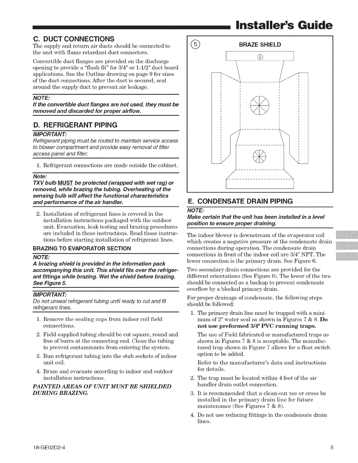
NOTE:
A brazing shield is provided in the information pack
accompanying this unit. This shield fits over the refriger-
ant fittings while brazing. Wet the shield before brazing.
See Figure 5.
IMPORTANT:
Do not unseal refrigerant tubing until ready to cut and fit
refrigerant lines.
!. Remove the sealing caps from indoor coil field
connections.
2. Field supplied tubing should be cut square, round and
free of burrs at the connecting end. Clean the tubing
to prevent contaminants from entering the system.
3. Run refrigerant tubing into the stub sockets of indoor
unit coil.
4. Braze and evacuate according to indoor and outdoor
installation instructions.
PAINTED AREAS OF UNIT MUST BE SHIELDED
DURING BRAZING.
@
BRAZE SHIELD
///-
i i
E. CONDENSATE DRAIN PiPiNG
NOTE:
Make certain that the unit has been installed in a level
position to ensure proper draining.
The indoor blower is downstream of the evaporator coil
which creates a negative pressure at the condensate drain
connections during operation. The condensate drain
connections in front of the indoor coil are 3/4" NPT. The
lower connection is the primary drain. See Figure 6.
Two secondary drain connections are provided for the
different orientations (See Figure 6). The lower of the two
should be connected as a backup to prevent condensate
overflow by a blocked primary drain.
For proper drainage of condensate, the following steps
should be followed:
!.
The primary drain line must be trapped with a mini-
mum of 2" water seal as shown in Figures 7 & 8. Do
not use preformed 3/4" PVC running traps.
The use of Field fabricated or manufactured traps as
shown in Figures 7 & 8 is acceptable. The manufac-
tured trap shown in Figure 7 allows for a float switch
option to be added.
Refer to the manufacturer's data and instructions
for details.
2. The trap must be located within 4 feet of the air
handler drain outlet connection.
3. It is recommended that a clean-out tee or cross be
installed in the primary drain line for future
maintenance (See Figures 7 & 8).
4. Do not use reducing fittings in the condensate drain
lines.
18-GE02D2-4 5