|nsta||er's Guide
®
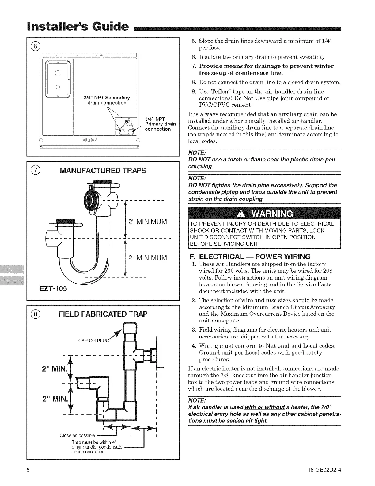
i 3/4 NPT Secondary
drain connection
3/4" NPT
Primary drain
connection
©
MANUFACTURED TRAPS
2" MINIMUM
r
=
2" MINIMUM
EZT-105
(_ FIELD FABRICATED TRAP
2" lVllN.
I
I
m =,
I
2" Mid ,I
I
I
I I
I
Close as possible
Trap must be within 4' [
of air handler condensate J
drain connection.
5. Slope the drain lines downward a minimum of 1/4"
per foot.
6. Insulate the primary drain to prevent sweating.
7. Provide means for drainage to prevent winter
freeze-up of condensate line.
8. Do not connect the drain line to a closed drain system.
9. Use Teflon ®tape on the air handler drain line
connections! Do Not Use pipe joint compound or
PVC/CPVC cement!
It is always recommended that an auxiliary drain pan be
installed under a horizontally installed air handler.
Connect the auxiliary drain line to a separate drain line
(no trap is needed in this line) and terminate according to
local codes.
NOTE:
DO NOT use a torch or flame near the plastic drain pan
coupling.
NOTE:
DO NOT tighten the drain pipe excessively. Support the
condensate piping and traps outside the unit to prevent
strain on the drain coupling.
TO PREVENT INJURY OR DEATH DUE TO ELECTRICAL
SHOCK OR CONTACT WITH MOVING PARTS, LOCK
UNIT DISCONNECT SWITCH IN OPEN POSITION
[BEFORE SERV C NG UN T.
F=
1.
ELECTRICAL m POWER WIRING
These Air Handlers are shipped from the factory
wired for 230 volts. The units may be wired for 208
volts. Follow instructions on unit wiring diagram
located on blower housing and in the Service Facts
document included with the unit.
2. The selection of wire and fuse sizes should be made
according to the Minimum Branch Circuit Ampacity
and the Maximum Overcurrent Device listed on the
unit nameplate.
3. Field wiring diagrams for electric heaters and unit
accessories are shipped with the accessory.
4. Wiring must conform to National and Local codes.
Ground unit per Local codes with good safety
procedures.
If an electric heater is not installed, connections are made
through the 7/8" knockout into the air handler junction
box to the two power leads and ground wire connections
which are located near the discharge of the blower.
NOTE:
ff air handler is used with or without a heater, the 7/8"
electrical entry hole as weft as any other cabinet penetra-
tions must be sealed air ti hghL.
6 18-G E02D2-4