Installer's Guide
G. CONTROL WIRING
!. Connect wiring between indoor unit, outdoor unit and
thermostat. The use of color-coded low-voltage wires
is recommended.
2. A low voltage terminal board is provided for control
wiring, and is located on the left side of the cross
brace in the center of the unit.
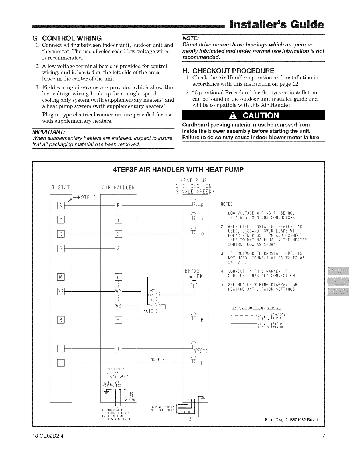
3. Field wiring diagrams are provided which show the
low voltage wiring hook-up for a single speed
cooling only system (with supplementary heaters) and
a heat pump system (with supplementary heaters).
Plug in type electrical connectors are provided for use
with supplementary heaters.
IMPORTANT:
When supplementary heaters are installed, inspect to insure
that all packaging material has been removed.
NOTE:
Direct drive motors have bearings which are perma-
nently lubricated and under normal use lubrication is not
recommended.
H. CHECKOUT PROCEDURE
!. Check the Air Handler operation and installation in
accordance with this instruction on page 12,
2, "Operational Procedure" for the system installation
can be found in the outdoor unit installer guide and
will be compatible with this Air Handler.
Cardboard packing material must be removed from
inside the blower assembly before starting the unit.
Failure to do so may cause indoor blower motor failure.
T'STAT
J
[Z]
[Z]
[Z]
%
%
[]
4TEP3F AIR HANDLER WITH HEAT PUMP
AIR
_NOTE 5
HANDLER
[Z]
[]
i
i
i
%
SEE NOTE 2
IPF_:],,,,/PM-A
SUPPL HTR. ]
CONTROL BOX
RED
FOR
/3 PH
J ODT" I
ODT-2
NOTE3
NOTE 4
TO POWER SUPPLY
PER LOCAL CODES &
AS DEFINED IN
FIELD WIRING TABLE
HEAT PUMP
O.D. SECTION
(SINGLE SPEED)
_--R
_--.y
_--0
BR/X2
OR BK
___
BR(T
I IlIP
f | H | H
TO POWER SUPPLY __
PER LOCAL CODES
NOTES:
I. LOW VOLTAGE WIRING TO BE NO.
18 A.W.G. MINIMUM CONDUCTORS.
WHEN FIELD-INSTALLED HEATERS ARE
USED, DISCARD POWER LEADS WITH
POLARIZED PLUG I-PM AND CONNECT
I-PF TO MATING PLUG iN THE HEATER
CONTROL BOX AS SHOWN.
3. IF OUTDOORTHERMOSTAT(ODT) IS
NOT USED, CONNECTWl TO W2 TO W3
ON LVTB.
4. CONNECT IN THIS MANNER IF
O.D. UNIT HAS "F" CONNECTION.
5. SEE HEATER WIRING DIAGRAM FOR
HEATING ANTICIPATOR SETTINGS.
INTER-COMPONENT WIRING
-24 V. FACTORY
= LINE v.jWIRING
24 V )FIELD
LINE V. WIRING
From Dwg. 21 B801082 Rev. 1
18-GE02D2-4 7