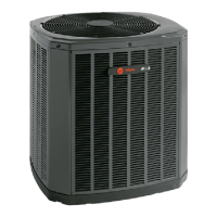
Do you have a question about the Trane 4TTR5018N and is the answer not in the manual?
| Model | 4TTR5018N |
|---|---|
| Type | Heat Pump |
| Cooling Capacity (tons) | 1.5 |
| Cooling Capacity (BTU/h) | 18000 |
| Heating Capacity (tons) | 1.5 |
| Heating Capacity (BTU/h) | 18000 |
| Refrigerant | R-410A |
| Voltage | 208/230 |
| Phase | 1 |
| Compressor Type | Scroll |
| Stages | Single Stage |
| Unit Weight (lbs) | 220 |
Details unit dimensions and weight for different models, including a table.
Specifies maximum refrigerant line length and vertical change limits.
Provides recommendations for outdoor unit placement to ensure airflow and reliability.
Addresses special requirements for installations near saltwater environments.
Details initial steps for unit preparation, including checking for damage and removal from pallet.
Outlines requirements and considerations for installing the unit on a support pad.
Provides a table detailing refrigerant line and service valve connection sizes by model.
Explains the factory charge for the outdoor unit and verification methods.
Instructs users to determine and record required refrigerant line length and lift.
Emphasizes the importance of insulating the vapor line and preventing contact.
Provides precautions for reusing existing refrigerant lines during retrofit.
Details precautions for routing refrigerant lines to prevent noise and ensure proper installation.
Provides step-by-step instructions for brazing refrigerant lines.
Details the procedure for checking refrigerant lines for leaks using nitrogen and soap solution.
Explains the process of evacuating the system using a micron gauge.
Provides instructions on how to open the gas service valve after checks are complete.
Details the procedure for safely opening the liquid service valve, including warnings.
Defines maximum lengths for low voltage wiring based on wire gauge.
Illustrates low voltage wiring connections for various thermostat and air handler configurations.
Details requirements for high voltage power supply and compliance with codes.
Recommends installing a separate disconnect switch for high voltage connections.
Specifies grounding requirements for the outdoor unit according to codes.
Outlines the steps for safely starting up the installed system.
Explains temperature measurements needed for system charge adjustment.
Provides charts and steps for adjusting system charge using subcooling method.
Details the weigh-in method for system charging when other methods are not feasible.
Lists essential checks and operational procedures after installation completion.
Illustrates the refrigeration circuit diagram for 5018 and 5024 model condensing units.
Shows the refrigeration circuit diagram for 5030 and 5036 model condensing units.
Presents the refrigeration circuit diagram for 5042 and 5048 model condensing units.
Displays the refrigeration circuit diagram for 5060 model condensing units.
Presents the wiring diagram for 4TTR5018 through 4TTR048 condensing units.
Provides the wiring diagram specific to the 4TTR5060 model condensing unit.
Shows pressure curves for the 4TTR5018N1 model under cooling conditions.
Displays pressure curves for the 4TTR5024N1 model during cooling operation.
Provides pressure curves for the 4TTR5030N1 model in cooling mode.
Shows pressure curves for the 4TTR5036N1 model for cooling applications.
Details pressure curves for the 4TTR5042N1 model under cooling conditions.
Presents pressure curves for the 4TTR5048N1 model during cooling operation.
Illustrates pressure curves for the 4TTR5060N1 model in cooling mode.
 Loading...