EasyManua.ls Logo

Trane 4TTX5018-060 User Manual

Trane 4TTX5018-060
28 pages
To Next Page IconTo Next Page
Page #1 background imageLoading...
Page #1 background image
18-AC124D1-1A-EN
ALL phases of this installation must comply with NATIONAL, STATE AND LOCAL CODES.
IMPORTANTThis Document is customer property and is to remain with this unit. Please return to service informa-
tion pack upon completion of work.
Condensing Units
These instructions do not cover all variations in systems or provide for every possible contingency to be met in connection with
the installation. Should further information be desired or should particular problems arise which are not covered sufficiently for the
purchaser’s purposes, the matter should be referred to your installing dealer or local distributor.
The manufacturer recommends installing only approved matched indoor and outdoor systems. All of the manufacture’s split
systems are A.H.R.I. rated only with TXV/EEV indoor systems. Some of the benefits of installing approved matched indoor and
outdoor split systems are maximum efficiency, optimum performance and the best overall system reliability.
4TTX5018 – 060
Installation and Operation Manual
Table of Contents
Section 1. Safety ..................................................................................... 2
Section 2. Unit Location Considerations ............................................. 3
Section 3. Unit Preparation.................................................................... 4
Section 4. Setting the Unit ..................................................................... 5
Section 5. Refrigerant Line Considerations ......................................... 5
Section 6. Refrigerant Line Routing ..................................................... 6
Section 7. Refrigerant Line Brazing ...................................................... 7
Section 8. Refrigerant Line Leak Check ............................................... 9
Section 9. Evacuation ............................................................................ 9
Section 10. Service Valves .................................................................. 10
Section 11. Electrical - Low Voltage ................................................... 10
Section 12. Electrical - High Voltage .................................................. 12
Section 13. Start Up.............................................................................. 12
Section 14. System Charge Adjustment............................................. 13
Section 15. Checkout Procedures ...................................................... 17
Section 16. Refrigeration Circuits........................................................18
Section 17. Wiring Diagrams................................................................20
Section 18. Pressure Curves................................................................24
Question and Answer IconNeed help?

Do you have a question about the Trane 4TTX5018-060 and is the answer not in the manual?
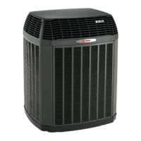
Trane 4TTX5018-060 Specifications

General IconGeneral
Model4TTX5018-060
TypeHeat Pump
Cooling Capacity (BTU/h)18000
RefrigerantR-410A
Voltage208/230
Phase1
Compressor TypeScroll

Summary

Section 1. Safety

General Safety Information

Essential safety warnings and precautions for installation and operation.

Section 2. Unit Location Considerations

Unit Dimensions and Weight

Details on unit size, weight, and mounting requirements.

Refrigerant Piping Limits

Guidelines for maximum refrigerant line length and vertical change.

Section 3. Unit Preparation

Prepare The Unit For Installation

Steps to prepare the unit for installation, including damage checks.

Section 4. Setting the Unit

Pad Installation

Requirements for installing the unit on a support pad or slab.

Section 5. Refrigerant Line Considerations

Refrigerant Line and Service Valve Connection Sizes

Table specifying line and valve connection sizes for different models.

Factory Charge

Information about the factory refrigerant charge for the outdoor unit.

Required Refrigerant Line Length

Procedure to determine required refrigerant line length and lift.

Section 6. Refrigerant Line Routing

Routing Precautions

Guidelines for properly routing refrigerant lines to prevent noise and damage.

Section 7. Refrigerant Line Brazing

Braze The Refrigerant Lines

Step-by-step instructions for brazing refrigerant lines to service valves.

Section 8. Refrigerant Line Leak Check

Check For Leaks

Procedure for pressurizing lines and checking for leaks using nitrogen.

Section 9. Evacuation

Evacuate Refrigerant Lines and Indoor Coil

Steps to evacuate the system to a specific micron level.

Section 10. Service Valves

Open the Gas Service Valve

Procedure for opening the gas service valve after leak check and evacuation.

Open the Liquid Service Valve

Procedure for opening the liquid service valve, including safety warnings.

Section 11. Electrical - Low Voltage

Low Voltage Maximum Wire Length

Table defining maximum lengths for low voltage wiring.

Low Voltage Hook-up Diagrams

Diagrams illustrating low voltage wiring connections for different thermostats.

Section 12. Electrical - High Voltage

High Voltage Power Supply

Guidelines for high voltage power supply, including safety warnings.

High Voltage Disconnect Switch

Recommendation to install a separate disconnect switch for high voltage.

High Voltage Ground

Requirements for grounding the outdoor unit.

Section 13. Start Up

System Start Up Procedure

Steps to follow for system start-up after installation.

Section 14. System Charge Adjustment

Temperature Measurements

Measuring outdoor and indoor temperatures for system charging.

Subcooling Charging in Cooling

Method for adjusting refrigerant charge using subcooling above 55°F outdoor temp.

Weigh-In Method for Charging

Alternative method for charging refrigerant, especially when subcooling is not feasible.

Section 15. Checkout Procedures

Operational and Checkout Procedures

Final checks and operational procedures to ensure proper performance.

Section 16. Refrigeration Circuits

Model Refrigeration Diagrams

Schematic diagrams of refrigeration circuits for different models.

Section 17. Wiring Diagrams

4TTX5018 - 048 Models Wiring

Wiring diagram for 4TTX5018 through 048 models.

4TTX5060 Models Wiring

Wiring diagram for 4TTX5060 models.

Section 18. Pressure Curves

Cooling Performance Curves (4TTX5018N1)

Pressure curves for cooling performance of 4TTX5018N1 model.

Cooling Performance Curves (4TTX5024N1 - 4TTX5048N1)

Pressure curves for cooling performance of 4TTX5024N1 to 4TTX5048N1 models.

Cooling Performance Curves (4TTX5060N1)

Pressure curves for cooling performance of 4TTX5060N1 model.

Related product manuals