Do you have a question about the Trane 4TTX7 and is the answer not in the manual?
Important safety warnings regarding electrical components, refrigerant handling, and compressor temperature.
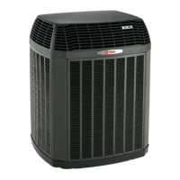
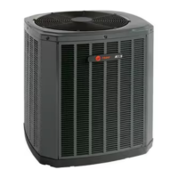
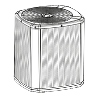
Details the physical size and weight of different condensing unit models.
Specifies maximum lengths and vertical changes for refrigerant lines.
Provides recommendations for optimal placement to ensure system reliability and airflow.
Outlines precautions for installations in areas with snow and freezing temperatures.
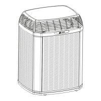
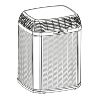
Describes the initial steps for preparing the condensing unit before installation.
Details requirements for installing the unit on a support pad.
Lists the correct sizes for vapor and liquid lines and service valve connections.
Information about the factory refrigerant charge and verification methods.
Instructions for measuring and recording line length for system calculations.
Emphasizes the importance of insulating the vapor line to prevent contact.
Precautions to take when using previously installed refrigerant lines.
Guidelines for routing refrigerant lines to prevent noise and ensure proper installation.
Step-by-step instructions for brazing refrigerant lines to service valves.
Procedure for pressurizing lines with nitrogen and checking for leaks.
Steps for evacuating the system to the required micron level.
Instructions on how to properly open the gas service valve.
Critical steps for opening the liquid service valve with safety warnings.
Table defining maximum wire lengths for low voltage connections based on gauge.
Wiring diagrams illustrating low voltage connections for various thermostats and air handlers.
Guidelines for connecting the high voltage power supply according to nameplate and codes.
Recommendation for installing a separate disconnect switch for high voltage connections.
Requirement to ground the outdoor unit according to national, state, and local codes.
Steps to follow for safely starting up the installed system.
Instructions for measuring outdoor and indoor temperatures for charge adjustment.
Procedure for adjusting system charge using subcooling method for outdoor temps above 55°F.
Recommended method for charging at outdoor temps below 55°F using weigh-in method.
A checklist of final operational and system checks after installation.
Schematic diagrams illustrating refrigerant flow for 2 and 3 ton units.
Schematic diagrams illustrating refrigerant flow for 4 ton units.
Schematic diagrams illustrating refrigerant flow for 5 ton units.
Wiring diagrams, legends, and connection details for 2 and 3 ton units.
Wiring diagrams, legends, and connection details for 4 ton units.
Wiring diagrams, legends, and connection details for 5 ton units.
Pressure curves for the 4TTX7024E1 unit during first stage cooling operation.
Pressure curves for the 4TTX7024E1 unit during second stage cooling operation.
Pressure curves for the 4TTX7036E1 unit during first stage cooling operation.
Pressure curves for the 4TTX7036E1 unit during second stage cooling operation.
Pressure curves for the 4TTX7048E1 unit during first stage cooling operation.
Pressure curves for the 4TTX7048E1 unit during second stage cooling operation.
Pressure curves for the 4TTX7060E1 unit during first stage cooling operation.
Pressure curves for the 4TTX7060E1 unit during second stage cooling operation.