EasyManua.ls Logo

Trane 4TTA4 - User Manual

Trane 4TTA4
30 pages
Print Icon
To Next Page IconTo Next Page
Loading...
18-AC108D1-1D-EN
ALL phases of this installation must comply with NATIONAL, STATE AND LOCAL CODES
IMPORTANTThis Document is customer property and is to remain with this unit. Please return to service informa-
tion pack upon completion of work.
These instructions do not cover all variations in systems or provide for every possible contingency to be met in connection with
the installation. Should further information be desired or should particular problems arise which are not covered sufficiently for the
purchaser’s purposes, the matter should be referred to your installing dealer or local distributor.
Note: The manufacturer recommends installing only approved matched indoor and outdoor systems. All of the manufacture’s split
systems are AHRI rated only with TXV/EEV indoor systems. Some of the benefits of installing approved matched indoor and out-
door split systems are maximum efficiency, optimum performance and the best overall system reliability.
4TTA4
Table of Contents
Section 1. Safety ..................................................................................... 2
Section 2. Unit Location Considerations ............................................. 3
Section 3. Unit Preparation .................................................................... 5
Section 4. Setting the Unit ..................................................................... 5
Section 5. Refrigerant Line Considerations ......................................... 6
Section 6. Refrigerant Line Routing ..................................................... 8
Section 7. Refrigerant Line Brazing ...................................................... 9
Section 8. Refrigerant Line Leak Check ............................................. 11
Section 9. Evacuation .......................................................................... 12
Section 10. Service Valves .................................................................. 12
Section 11. Electrical - Low Voltage ................................................... 13
Section 12. Electrical - High Voltage .................................................. 15
Section 13. Start Up .............................................................................. 16
Section 14. System Charge Adjustment ............................................. 17
Section 15. Checkout Procedures ...................................................... 23
Section 16. Refrigerant Circuits .......................................................... 23
Section 17. Wiring Diagrams ............................................................... 25
Section 18. Pressure Curves ............................................................... 29
Condensing Units
Installation and Operation Manual
Question and Answer IconNeed help?

Do you have a question about the Trane 4TTA4 and is the answer not in the manual?

Summary

Safety

Unit Location Considerations

Unit Dimensions and Weight

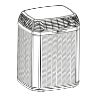
Provides physical dimensions and weight for various unit models.

Refrigerant Piping Limits

Specifies maximum total and vertical refrigerant line lengths allowed.

Suggested Locations for Best Reliability

Advises on optimal placement to ensure unit performance and longevity.

Cold Climate Considerations

Provides precautions for installing units in cold weather environments.

Coastal Considerations

Recommends protective kits for units installed near saltwater.

Unit Preparation and Refrigerant Line Installation

Prepare The Unit For Installation

Outlines essential steps for inspecting and preparing the unit before installation.

Setting the Unit

Details requirements for properly setting the outdoor unit on its support pad.

Refrigerant Line Considerations

Covers line sizes, factory charge, insulation, and reusing lines.

Refrigerant Line Routing

Details proper methods for routing refrigerant lines to prevent noise and vibration.

Refrigerant Line Brazing

Step-by-step guide for securely brazing refrigerant lines.

System Checks and Service Procedures

Refrigerant Line Leak Check

Procedure for detecting leaks in the refrigerant lines using nitrogen and soap.

System Evacuation

Explains how to evacuate the system to remove moisture and non-condensables.

Service Valves Operation

Instructions on how to safely open and close service valves.

Electrical System Installation

Low Voltage Electrical Connections

Covers low voltage wiring requirements and diagrams.

High Voltage Electrical Connections

Details high voltage power supply, disconnect, and grounding.

System Start-Up and Charge Adjustment

System Start Up

Step-by-step procedure for initial system start-up after installation.

System Charge Adjustment (Above 55° F)

Procedure for charging using subcooling method in warmer temperatures.

System Charge Adjustment (Below 55° F)

Recommended weighing-in method for charging at temperatures below 55°F.

Final Procedures, Diagrams, and Performance

Checkout Procedures

Final operational and system checkout checklist.

Refrigerant Circuits Diagrams

Illustrates refrigerant flow diagrams for different unit capacities.

Wiring Diagrams

Wiring diagrams for specific unit models and configurations.

Liquid Pressure Curves

Charts for verifying system performance based on liquid pressure and temperature.

Suction Pressure Curves

Charts for verifying system performance based on suction pressure and temperature.

Liquid Pressure Curves (Additional Models)

Displays liquid pressure vs. outdoor temp for other models.

Suction Pressure Curves (Additional Models)

Shows suction pressure vs. outdoor temp for other models.

Overview

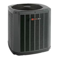
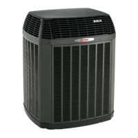
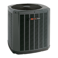
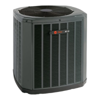
This document outlines the installation and operation procedures for Trane 4TTA4 series condensing units, providing comprehensive guidance for technicians and installers. The primary function of these units is to serve as the outdoor component of a split central air conditioning system, working in conjunction with an indoor evaporator coil and air handler or furnace to provide cooling for residential and commercial applications.

Function Description

The Trane 4TTA4 condensing units are designed to efficiently remove heat from indoor spaces and dissipate it outdoors. They utilize R-410A refrigerant, a hydrofluorocarbon (HFC) blend that operates at higher pressures than older refrigerants like R-22. This design choice contributes to improved energy efficiency and environmental performance. The units are factory-charged with a specific amount of R-410A, sufficient for the outdoor unit, ten feet of connecting line, and the smallest rated indoor evaporative coil match. Proper system charging is crucial for optimal performance and is verified via subcooling (for TXV/EEV indoor systems) or superheat (for fixed orifice indoor systems), as detailed on the unit nameplate.

The condensing unit houses a scroll compressor, which is a key component responsible for compressing the refrigerant. The outdoor coil facilitates heat exchange with the ambient air, while a fan circulates air over the coil to enhance this process. The system also includes service valves for both the liquid and vapor lines, allowing for connection of refrigerant lines, pressure measurement, and charging/recovery operations.

Usage Features

The installation process for the 4TTA4 condensing units is designed to be straightforward yet thorough, with detailed steps to ensure safe and efficient operation.

  • Location Considerations: The manual provides guidelines for optimal unit placement, emphasizing the need for unrestricted airflow around the unit, adequate clearance from structures and shrubbery, and consideration for noise levels to avoid disturbing occupants. For installations in cold climates, recommendations include elevating the unit to prevent snow accumulation and installing snow drift barriers if necessary. Special considerations are also outlined for coastal installations, requiring the addition of a Seacoast Salt Shield kit.
  • Unit Preparation: Before installation, technicians are instructed to inspect the unit for any shipping damage and to remove it from its pallet by cutting specific tabs.
  • Pad Installation: The unit should be placed on a level support pad, such as a concrete slab, that is at least one inch larger than the unit on all sides and separate from the building structure to prevent vibration transmission.
  • Refrigerant Line Installation: The manual specifies maximum total refrigerant line lengths (150 feet) and vertical lift (50 feet), along with standard and alternate line sizes. It stresses the importance of insulating the vapor line and preventing direct metal-to-metal contact between the liquid and vapor lines. For retrofit applications, existing refrigerant lines can be reused if they are the correct size, free of leaks, acid, and oil, and all joints are brazed, not soldered.
  • Refrigerant Line Routing: Precautions are outlined to prevent noise and vibration transmission within the building structure. This includes using isolation hangers when fastening lines to joists or framing, insulating lines run through walls or sills, and minimizing 90-degree turns.
  • Refrigerant Line Brazing: A step-by-step brazing procedure is provided, emphasizing the importance of deburring and cleaning pipe ends, purging with dry nitrogen to prevent oxidation, and wrapping valve bodies with wet rags to prevent heat damage. For units with field-installed external driers, the correct directional flow must be confirmed before brazing.
  • Leak Check and Evacuation: After brazing, the refrigerant lines and indoor coil must be pressurized with dry nitrogen to 150 PSIG and checked for leaks using a soapy solution. Following a successful leak check, the system must be evacuated to a vacuum of no higher than 350 microns, verified by observing the micron gauge for at least one minute.
  • Service Valve Operation: Detailed instructions are provided for opening both the gas and liquid service valves, including the specific number of turns and precautions to prevent refrigerant release and personal injury.
  • Electrical Connections: The manual covers both low and high voltage electrical connections. It specifies maximum wire lengths for low voltage wiring based on wire gauge and emphasizes compliance with national, state, and local codes. A separate disconnect switch is required at the outdoor unit, and flexible electrical conduit is recommended for high voltage connections to minimize vibration transmission. Proper grounding of the outdoor unit is also mandated.
  • System Start-Up: A sequence for system start-up is provided, including setting the thermostat to OFF, applying power, waiting one hour if a crankcase heater accessory is used and the ambient temperature is below 70°F, and then setting the thermostat to ON.
  • System Charge Adjustment: This is a critical step for optimal performance. For outdoor temperatures above 55°F, subcooling charging is the recommended method. The manual includes charts to determine the final subcooling value based on total line length and lift. For temperatures below 55°F, the weigh-in method is recommended, calculating additional charge based on line length beyond the factory-charged ten feet. The importance of stabilizing the system for at least 20 minutes before making accurate measurements is highlighted.

Maintenance Features

While the manual primarily focuses on installation and initial start-up, several aspects contribute to the long-term maintainability and reliability of the unit.

  • Safety Warnings: Throughout the document, prominent warnings highlight potential hazards, such as working with live electrical components, handling R-410A refrigerant at high pressures, and the hot dome temperatures of scroll compressors. These warnings are crucial for ensuring the safety of technicians during installation and future servicing.
  • Refrigerant Handling: The manual emphasizes the use of R-410A approved service equipment and the hygroscopic nature of POE oil used with R-410A. It advises against breaking a vacuum with air and recommends changing driers when opening the system for component replacement, which are critical practices for maintaining system integrity and preventing moisture contamination.
  • Leak Check and Evacuation Procedures: The detailed procedures for leak checking and evacuation are fundamental maintenance practices that ensure the system is free of leaks and moisture, which are common causes of system failure and reduced efficiency.
  • System Charge Adjustment: The comprehensive guidance on system charge adjustment ensures that the unit operates at its designed efficiency and capacity. Regular verification of the charge during maintenance checks is essential.
  • Checkout Procedures: The final checkout procedures provide a checklist for installers to verify various aspects of the installation, including refrigerant line integrity, insulation, electrical connections, airflow, and overall system operation. This ensures that the unit is left in optimal working condition, reducing the likelihood of future service calls.
  • Wiring Diagrams: Detailed wiring diagrams for different models (036A3, 042A3, 048A3, 060A3, 036A4, 042A4, 048A4, 060A4) are included, which are invaluable for troubleshooting and maintenance by providing a clear understanding of the unit's electrical components and connections.
  • Pressure Curves: The inclusion of pressure curves allows technicians to verify typical performance during maintenance. By comparing measured liquid and suction pressures against the curves for specific outdoor and indoor wet bulb temperatures, technicians can diagnose potential issues and ensure the system is operating within its design parameters.
  • Service Valve Design: The service valves are designed for ease of access for pressure measurement and refrigerant handling, facilitating future maintenance tasks. The instruction to replace valve stem caps and tighten them properly after servicing helps prevent refrigerant leaks.

In summary, the Trane 4TTA4 condensing unit manual provides a robust framework for installation, ensuring that the units are set up for reliable and efficient operation. The emphasis on proper refrigerant handling, electrical safety, and detailed checkout procedures contributes significantly to the long-term maintainability and performance of these air conditioning systems.

Trane 4TTA4 Specifications

General IconGeneral
RefrigerantR-410A
Voltage (V)208/230
Phase1
TypeHeat Pump
StagesSingle-Stage

Related product manuals