Do you have a question about the Trane 4TTB3-D and is the answer not in the manual?
Use only R-410A refrigerant and approved POE compressor oil for service.
Unit must be positioned minimum 12" from wall/shrubbery for adequate airflow.
Guidelines for routing, bending, securing, and insulating refrigerant lines.
Details on brass liquid and gas line service valves.
How to open the liquid line service valve, caution on stem contact.
How to open the gas line ball service valve.
Steps to evacuate the system to 350 microns.
Guidance on wire size and maximum length for control wiring.
Steps for setting thermostat and applying power for compressor start-up.
Inspect tubing, connections, and wiring for secure installation.
Identifies system faults and their primary/secondary causes.
Subcooling is recommended for charging above 55°F ambient.
Table for determining refrigerant charge based on liquid temp and subcooling.
Correction tables for line length and height (lift) adjustments.
Table providing dimensions for various models.
Diagram showing mounting hole positions and dimensions.
List of checks to perform after installation for system operation.
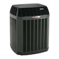
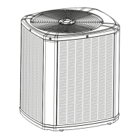
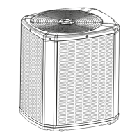
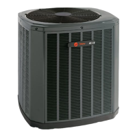
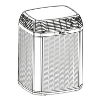
This document describes the installation, operation, and maintenance of Trane 4TTB3-D series condensing units, which are designed for central air conditioning systems. The guide emphasizes compliance with all national, state, and local codes throughout the installation process.
The Trane 4TTB3-D condensing units are integral components of a central air conditioning system, working in conjunction with an indoor air handler or coil to provide cooling. These units utilize R-410A refrigerant, which operates at higher pressures than older R-22 systems, necessitating specific service equipment and procedures. The primary function is to compress and condense the refrigerant, releasing heat to the outdoor environment, thereby facilitating the cooling cycle within the building. The units are designed for optimal performance when paired with Trane-approved matched indoor and outdoor systems, ensuring maximum efficiency and reliability.
The installation process begins with proper placement of the condensing unit. It must be set on a level support pad, at least as large as the unit's base pan, and positioned a minimum of 12 inches from any wall or surrounding shrubbery to ensure adequate airflow. The top discharge area requires at least five feet of unrestricted space above the unit. If mounted on a roof, the structure must be capable of supporting the unit's weight, and isolation is recommended to prevent sound or vibration transmission.
Refrigerant line installation is a critical step. The guide specifies using braze connections rather than soldered joints for existing lines. Pressure taps are provided on the service valves for monitoring compressor suction and liquid pressures. The gas line must always be insulated. For scroll compressor applications, users are warned that dome temperatures may be hot, and direct contact should be avoided to prevent burns.
The units are factory-charged with R-410A refrigerant, sufficient for the outdoor unit, 15 feet of connecting line, and the smallest indoor evaporative coil match. Adjustments to the refrigerant charge are necessary if the connecting line length exceeds 15 feet or if a larger indoor evaporative coil is installed. Subcooling in cooling mode is the recommended charging method for outdoor temperatures above 55°F, with indoor temperatures ideally maintained between 70°F and 80°F for best results.
Service valve operation involves specific procedures. The brass liquid and gas line service valves are shipped in a seated position to hold the factory charge. The pressure tap service port opens only to the field brazing side when the valve is seated. Extreme caution is advised when opening the liquid line service valve; the stem should be turned counterclockwise only until it contacts the rolled edge, without applying torque. The gas line ball service valve is fully opened with a 1/4 turn.
Brazing refrigerant lines requires removing lower access covers, cleaning external and internal surfaces of stub tubes, and cutting/fitting tubing to minimize sharp bends. The entire gas line and its fittings must be insulated, and the uninsulated liquid line should not contact the bare gas line. Precautions are necessary to prevent heat damage to the pressure tap valve core during brazing, including removing the core and wrapping a wet rag around the valve body. A dry nitrogen purge and brazing alloy without flux should be used during brazing.
After brazing, a leak check is performed by pressurizing the system with dry nitrogen to 350-400 psi and checking all field joints with soap bubbles. If leaks are found, pressure must be released, and repairs made. System evacuation follows, where refrigerant lines and the indoor coil are evacuated to no higher than 350 microns using a vacuum pump. The guide emphasizes not venting refrigerant into the atmosphere.
Electrical connections must comply with local codes, and the power supply must match the unit's nameplate. A separate disconnect switch is required at the outdoor unit, and the unit must be grounded. Flexible electrical conduit is recommended to prevent vibration transmission. Color-coded low voltage wiring simplifies connections between the outdoor unit, thermostat, and indoor unit. The maximum wire length for low voltage wiring varies by gauge (18 AWG: 150 ft, 16 AWG: 225 ft, 14 AWG: 300 ft).
Compressor start-up involves setting the thermostat system switch to OFF, applying power to activate the compressor sump heat (if present) for one hour before changing the thermostat setting to allow the compressor to run. This prevents potential compressor overload trips.
Operational and checkout procedures include a final unit inspection to ensure factory tubing has not shifted during shipment, adjusting it if necessary to prevent rubbing. Wiring connections must be tight and secure. The system should be operated in each mode to ensure safe operation.
The document highlights several maintenance-related checks as part of the checkout procedure. These include verifying that refrigerant lines are leak-checked, suction lines and fittings are properly insulated, and all refrigerant lines are secured and isolated. Passages through masonry should be sealed to prevent mortar from contacting copper tubing. All electrical connections must be tight. The outdoor fan's operation should be observed for clearance and smooth functioning. The indoor coil drain line must drain freely, which can be checked by pouring water into the drain pan. Supply registers and return grilles should be open and unobstructed, and the return air filter must be installed. The thermostat thermometer's accuracy should be checked against a reliable thermometer and adjusted if needed. The correct speed tap for the indoor blower motor should be verified.
For units installed within one mile of salt water, including seacoasts and inland waterways, the addition of a Seacoast Kit (BAYSEAC001) is required for models without factory-supplied Seacoast Salt Shields, to protect against corrosion.
The troubleshooting chart provides a guide to diagnosing system faults, categorizing them into refrigerant circuit issues (e.g., high/low pressures, inefficient compressor, restrictions) and electrical problems (e.g., compressor/fan not starting, compressor hums but won't start, compressor cycles on IOL). For each fault, primary and secondary causes are listed, such as run capacitor, start capacitor, contactor contacts, control transformer, low voltage fuse, refrigerant undercharge/overcharge, noncondensables, restricted airflow, and TXV issues. This chart serves as a valuable tool for technicians to identify and resolve common problems efficiently.
The guide also provides detailed subcooling charging tables for various unit tonnages (1.5, 2, 2.5, 3, 3.5, 4, and 5 tons), including corrections for line length and rise. These tables are crucial for accurately adjusting the refrigerant charge to ensure optimal system performance and efficiency. The importance of replacing valve stem caps and pressure tap caps finger tight, then tightening an additional 1/6 turn, is stressed to prevent leaks.
| Model | 4TTB3-D |
|---|---|
| Type | Heat Pump |
| SEER Rating | Up to 16 |
| Refrigerant | R-410A |
| Voltage | 208/230V |
| Cooling Capacity | 2-5 Tons |
| Heating Capacity | 2-5 Tons |
| Compressor Type | Scroll |
| Stages | Single-Stage |