Do you have a question about the Trane 4TWZ0 series and is the answer not in the manual?
Warning about hazards of live electrical components during installation, testing, or servicing.
Safety precautions for R-410A refrigerant, POE oil, and system handling to prevent moisture absorption.
Cautions regarding brazing existing lines and hot compressor dome temperatures.
Cautionary advice for operating liquid line service valves to prevent injury or damage.
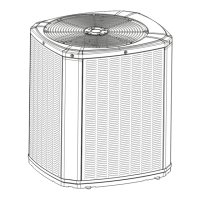
Provides dimensions and weight specifications for various Trane models.
Details maximum refrigerant line length and vertical change limits for system installation.
Offers recommendations for outdoor unit placement to ensure optimal performance and minimize noise.
Provides specific installation advice for heat pumps in cold climates to manage snow and ice.
Outlines steps for inspecting the unit for damage and removing it from its packaging.
Details requirements for installing the outdoor unit on a support pad, ensuring levelness and drainage.
Lists connection sizes for vapor and liquid lines and service valves for different models.
Explains factory refrigerant charge and when adjustments are necessary based on line length and coil.
Instructions to determine and record line length and vertical lift for charge adjustment calculations.
Emphasizes the importance of insulating the vapor line and preventing contact between lines.
Provides precautions for using existing refrigerant lines in retrofit applications.
Advises on routing refrigerant lines to prevent noise transmission and ensure proper isolation.
Step-by-step guide for preparing and brazing refrigerant lines to service valves.
Details the process of leak checking refrigerant lines using nitrogen pressure and soap solution.
Explains the procedure for evacuating the system to a specific micron level.
Instructions on how to properly open the gas service valve after system evacuation.
Step-by-step guide for safely opening the liquid line service valve.
Provides a table and notes on maximum wire lengths for low voltage and communicating systems.
Illustrates low voltage wiring connections for communicating systems with different indoor units.
Shows wiring diagrams for TAM7 Air Handler with 24 Volt control for AC/Heat Pump.
Continues the wiring diagrams for TAM7 Air Handler control board configurations.
Illustrates low voltage wiring for communicating indoor units with furnaces or air handlers.
Explains the demand defrost control mechanism and pin identification for heat pumps.
Covers high voltage power supply requirements, compliance, and wiring diagram location.
Recommends installing a separate disconnect switch for high voltage connections.
Details grounding requirements for the outdoor unit according to codes.
Provides a step-by-step guide for initiating system operation after installation.
Explains how to measure temperatures for system charging procedures.
Details the subcooling method for charging systems in cooling mode above 55°F.
Provides tables to correct subcooling charge based on line length, lift, and dip switch settings.
Outlines the choice between Charge Assist™™ or manual charging procedures.
Step-by-step guide for using the Charge Assist™™ tool for system charging.
Details the manual charging process for cooling mode within specific ambient temperature ranges.
Presents a charging chart for 3-ton AC units to determine proper liquid gage pressure.
Collection of charging charts for various AC and HP models and tonnages.
Steps for adding or recovering refrigerant to match charging chart values.
Instructions for stabilizing the system after adjustments and verifying charge.
Guidance to verify system performance using Service Facts curves.
Procedure for subcooling charge adjustment in heating mode for low outdoor temperatures.
Steps to measure suction line pressure and temperature for superheat calculation.
A chart to determine target superheat based on suction line temperature and pressure.
Steps to adjust refrigerant level to achieve the target superheat.
Final steps for system stabilization and completion after superheat adjustment.
Guidance on targeting subcooling levels as a reference.
Instructions to verify system performance using Service Facts curves.
Lists final inspection and operational checks for the installed system.
Provides a system fault guide, listing potential causes for various operational issues.
| Series | 4TWZ0 |
|---|---|
| Refrigerant | R-410A |
| Voltage | 208/230V |
| Phase | 1 |
| Type | Air Conditioner |
| Warranty | 10 year limited warranty on compressor |