EasyManua.ls Logo

Trane 4TWV7X24A1000A User Manual

Trane 4TWV7X24A1000A
32 pages
To Next Page IconTo Next Page
Page #1 background imageLoading...
Page #1 background image
SSAAFFEETTYY WWAARRNNIINNGG
Only qualified personnel should install and service the equipment. The installation, starting up, and servicing of heating, ventilating, and air-conditioning
equipment can be hazardous and requires specific knowledge and training. Improperly installed, adjusted or altered equipment by an unqualified person
could result in death or serious injury. When working on the equipment, observe all precautions in the literature and on the tags, stickers, and labels that
are attached to the equipment.
April 2023
1188--BBCC111111DD11--11AA--EENN
TRANE Link Variable Speed Heat Pumps and Air
Conditioners
4TWV7X24A1000A
4TWV7X36A1000A
4TWV7X48A1000A
4TWV7X60A1000A
4TTV7X24A1000A
4TTV7X36A1000A
4TTV7X48A1000A
4TTV7X60A1000A
TM
The Diagnostics Mobile App is available by scanning a QR
code located inside this unit or by searching for the Trane or
American Standard Diagnostics App in your App Store
®
.
This system must include a A/T HUI2360A200U thermostat
and a TSYS2C60A2VVU system controller to operate and is
Link communicating only.
NNoottee:: “Graphics in this document are for representation
only. Actual model may differ in appearance.”
Installer’s Guide
Question and Answer IconNeed help?

Do you have a question about the Trane 4TWV7X24A1000A and is the answer not in the manual?

Trane 4TWV7X24A1000A Specifications

General IconGeneral
BrandTrane
Model4TWV7X24A1000A
CategoryAir Conditioner
LanguageEnglish

Summary

Safety Section

Hazardous Voltage

Warns about property damage, severe injury, or death from electrical hazards.

Refrigerant Handling and Safety

Details hazards of refrigerant oil and high-pressure refrigerant handling.

Electrical Safety and Grounding

Covers proper grounding, safe service valve operation, brazing, and leakage current.

Unit Location Considerations

Unit Dimensions and Weight

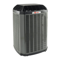
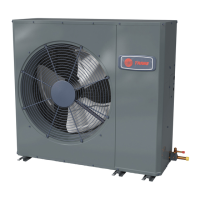
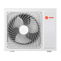
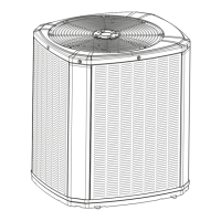
Provides dimensions and weight for different outdoor unit models.

Suggested Locations

Details optimal placement for best reliability, considering airflow and obstructions.

Cold Climate and Coastal Considerations

Addresses installation precautions for cold climates and coastal environments.

Unit Preparation

Setting Up the Unit

Instructions for unit setup, including pad installation requirements.

Refrigerant Line Considerations

Refrigerant Line Insulation

Important guidelines for insulating liquid and vapor lines to maintain performance.

Refrigerant Line Routing Precautions

Precautions for routing lines, including isolation from structural elements.

Reuse of Existing Refrigerant Lines

Precautions for using existing refrigerant lines, ensuring proper brazing and cleanliness.

Refrigerant Line Brazing

Braze the Refrigerant Lines

Step-by-step instructions for brazing refrigerant lines, including preparation and purging.

Refrigerant Line Leak Check

Leak Check and Evacuation Procedures

Steps for pressurizing, checking for leaks, and evacuating the refrigerant system.

Service Valves

Opening Gas and Liquid Service Valves

Procedures for opening gas and liquid service valves safely and correctly.

Low Voltage Communicating Wiring

Wire Length and Connectors

Guidelines for maximum wire length and using low voltage wire connectors.

Hook-up Diagrams

Illustrates low voltage hook-up diagrams for Link mode systems.

High Voltage Electrical Connections

Power Supply and Disconnect Switch

Information on high voltage power supply, disconnect switch, and grounding requirements.

Control Board LED Indicators

AOC and MOC Flash Codes

Explains LED flash codes for AOC and MOC status and communication.

System Start Up Procedures

Initial Start Up Steps

Steps for initial system startup, including thermostat settings and power application.

System Charge Adjustment

Temperature Measurements and Corrections

Procedures for taking temperature measurements and applying subcooling corrections for charging.

Subcool Charging Correction Charts

Charts for Different Tonnages

Provides graphical charts for subcooling corrections based on line length and lift for various tonnages.

Refrigerant Charging Chart

R-410A Subcooling Chart

Table detailing R-410A refrigerant charging based on liquid temperature and design subcooling.

Charging the Unit

Proper Gage Pressure and Stabilization

Steps for achieving proper gage pressure and stabilizing the system during charging.

Performance Verification

Guidance on verifying system performance using pressure curves.

Subcooling Charging Below 55° F Outdoor Temp (Heating Only)

Weigh-In Method for Heating Mode

Explains the weigh-in method for charging in heating mode below 55°F.

GET THE APP

Diagnostics Mobile App Usage

Information on downloading and using the Trane/American Standard Diagnostics Mobile App.

Defrost Control (Heat Pump Only)

Demand Defrost and Fault Identification

Explains demand defrost operation, sensor inputs, and fault identification methods.

Forced Defrost Procedures

Details how to initiate and monitor a forced defrost cycle using the thermostat or app.

Checkout Procedures

Final Installation Checks

A checklist of final installation checks to ensure proper operation and safety.

Notices and Compliance

FCC and IC Compliance

Regulatory notices regarding FCC and Industry Canada compliance for the device.

Related product manuals