EasyManua.ls Logo

Trane 4TWL6036A1000A User Manual

Trane 4TWL6036A1000A
28 pages
To Next Page IconTo Next Page
Page #1 background imageLoading...
Page #1 background image
SSAAFFEETTYYWWAARRNNIINNGG
Only qualified personnel should install and service the equipment. The installation, starting up, and servicing of heating, ventilating, and
air-conditioning equipment can be hazardous and requires specific knowledge and training. Improperly installed, adjusted or altered
equipment by an unqualified person could result in death or serious injury. When working on the equipment, observe all precautions in the
literature and on the tags, stickers, and labels that are attached to the equipment.
February 2020
1188--BBCC9999DD11--11DD--EENN
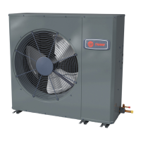
Side Discharge HP Models
For coastal applications where units are installed within one (1) mile of salt water, epoxy coated models are recommended.
These models have an 8 week lead time after order.
EEppooxxyyCCooaatteeddMMooddeell
4TWL6018A1000A
4TWL6024A1000A
4TWL6030A1000A
4TWL6036A1000A
4TWL6042A1000A
4TWL6048A1000A
4TWL6060A1000A
4TWL6018A1COTA
4TWL6024A1COTA
4TWL6030A1COTA
4TWL6036A1COTA
4TWL6042A1COTA
4TWL6048A1COTA
4TWL6060A1COTA
NNoottee:: “Graphics in this document are for representation
only. Actual model may differ in appearance.”
Installer’s Guide
Other manuals for Trane 4TWL6036A1000A

Questions and Answers:

Trane 4TWL6036A1000A Specifications

General IconGeneral
BrandTrane
Model4TWL6036A1000A
CategoryAir Conditioner
LanguageEnglish

Summary

Side Discharge HP Models

Coastal Application Recommendation

Recommends epoxy coated models for coastal areas, noting lead time.

Safety Section

Electrical and Refrigerant Safety Warnings

Covers hazardous voltage, refrigerant oil, hot surfaces, and refrigerant handling.

Grounding, Brazing, and Valve Precautions

Emphasizes grounding, brazing for lines, and service valve handling.

Chemical Exposure Warning

Warns about potential exposure to harmful chemicals like lead.

Unit Location Considerations

Unit Dimensions and Weight

Table detailing unit dimensions (H x D x W) and weight for various models.

Refrigerant Piping Limits

Specifies maximum refrigerant line length and vertical change limits.

Suggested Locations for Best Reliability

Recommendations for unit placement to ensure optimal airflow and performance.

Climate Considerations

Precautions for cold climates and coastal installation, including epoxy coils.

Unit Preparation and Setup

Unit Inspection and Pallet Removal

Steps for checking damage and removing the unit from its pallet.

Pad Installation Guidelines

Guidelines for selecting and installing the unit support pad for drainage and stability.

Refrigerant Line Considerations

Line Sizes and Factory Charge

Details line sizes, service valve connections, and factory charge information.

Refrigerant Line Length and Lift

Worksheet to determine line length and lift for charging calculations.

Refrigerant Line Insulation and Routing

Requirements for insulating lines, preventing contact, and routing precautions.

Reuse Existing Refrigerant Lines

Precautions for reusing existing refrigerant lines in retrofit applications.

Refrigerant Line Isolation Methods

Techniques for isolating lines from structural elements and ductwork.

Refrigerant Line Brazing

Brazing Procedure

Step-by-step guide for preparing and brazing refrigerant lines.

Brazing Procedure (Continued)

Continues brazing steps, including drier installation and heat protection.

Refrigerant Line Leak Check

Leak Detection and System Evacuation

Procedure for leak checking with nitrogen and evacuating the system to microns.

Service Valves

Opening Gas and Liquid Service Valves

Instructions for safely opening gas and liquid service valves.

Electrical - Low Voltage

Low Voltage Wiring and Hook-up

Covers wire length limits and hook-up diagrams for non-communicating systems.

Electrical - High Voltage

High Voltage Power Supply and Disconnect

Warnings and requirements for high voltage power supply and disconnect switches.

System Start Up

Start-Up Sequence

Step-by-step procedure for starting the unit, including thermostat and power settings.

Subcooling Charging in Cooling

Charging Method and Stabilization

Subcooling method, indoor temperature, and stabilization requirements for charging.

Refrigerant Adjustment Procedure

Steps to measure conditions and add/remove refrigerant based on subcooling charts.

System Charge Adjustment

Temperature Measurement and Correction Worksheet

Guidelines for temperature measurements and worksheet for subcooling corrections.

Refrigerant Charging Chart

R-410A Charging Data

Chart correlating liquid temperature, design subcooling, and liquid gauge pressure.

Subcool Charging Charts

Charging Corrections by Model Tonnage

Charts providing subcooling corrections for various tonnage models based on line length and lift.

Charging the Unit

System Stabilization and Verification

Procedures for stabilizing the system, verifying pressures, and checking performance curves.

Refrigerant Adjustment and System Data

Adjusting refrigerant and recording system information after charging.

Checkout Procedures

Installation Checklist

Comprehensive checklist covering wiring, refrigerant lines, ductwork, and system function.

Troubleshooting

Compressor Start Failure Diagnosis

Flowchart for diagnosing issues when the compressor fails to start.

Compressor Operation Diagnosis

Flowchart for diagnosing issues when the compressor runs but doesn't operate correctly.

Related product manuals