EasyManua.ls Logo

Trane 4TXFH024CZ3HHA - User Manual

Trane 4TXFH024CZ3HHA
6 pages
Print Icon
To Next Page IconTo Next Page
Loading...
A. GENERAL
These coils are designed for use as cooling only or in
combination with a Heat Pump outdoor section.
B. APPLICATION INFORMATION
1. FURNACE AND COIL
Coil MUST BE installed downstream (discharge air)
of the furnace.
2. INDOOR UNIT AIRFLOW
Indoor unit must provide the required airow for
Cooling only or Heat Pump System Combination.
INSPECTION
Check carefully for any shipping damage. This must be
reported to and claims made against the transportation
com pany immediately. Check to be sure all major
components are in the unit. Any missing parts should
be reported to your supplier at once, and replaced with
authorized parts only.
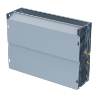
Horizontal, Flat “Cased” Coils
All Aluminum Coils: 4TXFH024CZ3HH*, 4TXFH033CC3HH*,
4TXFH036CZ3HH*, 4TXFH041CC3HH*, 4TXFH054CC3HH*,
4TXFH063CZ3HH*, 4TXFH064AZ3HHA ** May be "A" or "B"
Installers Guide
C. RECOMMENDATIONS
CAUTION
!
This coil is pressurized with 8-12 psig of dry air. Do
not stand directly in front of the coil connections when
removing sealing plugs. If no pressure is released,
check for leaks.
1. If this coil is a part of the total system installation, then
use the Installer’s Guide packaged with the furnaces,
Heat Pump outdoor sections, and Control Center for
physically installing those components.
2. It is recommended that the outline drawing
(page 2) be studied and dimensions properly noted
and checked against selected installation site. By
noting in advance proper clearance allowances for
installation and possible future service of the coil.
A341869P36
ALL phases of this installation must comply with NATIONAL, STATE AND LOCAL CODES
IMPORTANT — This Document is customer property and is to remain with this unit. Please return to service information pack
upon completion of work.
18-AD25D1-4C-EN
WARNING
!
This product can expose you to chemicals including lead, which
are known to the State of California to case cancer and birth defects
or other reproductive harm. For more information go to www.
P65Warnings.ca.gov
D. INSTALLING 4TXFH COIL /
ENCLOSURE
Coil/enclosure assembly can be used for all horizontal
furnaces (gas and electric) applications (Figure 1), and
for applications of vertical upow furnaces (Figure 2),
where the top clearance is insu󰀩cient for installing an
“A” coil and enclosure, and there is access to a run of
horizontal duct.
SUPPLY DUCT
2 FEET MINIMUM
RECOMMENDED
FURNACE
FLUE STACK
TRANSITION DUCT
COIL/ENCLOSURE ASSY
WARNING
!
WARNING (Medium/high pressure)
Contains Refrigerant!
System contains oil and refrigerant under high pressure. Recover
refrigerant to relieve pressure before opening the system. See
unit nameplate for refrigerant type. Do not use non-approved
refrigerants, refrigerant substitutes, or refrigerant additives.
Failure to follow proper procedures or the use of non-approved
refrigerants, substitutes, or refrigerant additives could result in
death, serious injury, or equipment damage.
Question and Answer IconNeed help?

Do you have a question about the Trane 4TXFH024CZ3HHA and is the answer not in the manual?

Overview

This document provides an installer's guide for horizontal, flat "cased" coils, specifically the All Aluminum Coils series: 4TXFH024CZ3HH*, 4TXFH033CC3HH*, 4TXFH036CZ3HH*, 4TXFH041CC3HH*, 4TXFH054CC3HH*, 4TXFH063CZ3HH*, and 4TXFH064AZ3HHA (where * may be "A" or "B").

This guide emphasizes that all phases of installation must comply with national, state, and local codes. It is an important document that is customer property and should remain with the unit, to be returned to the service information pack upon completion of work.

Function Description:

These coils are designed for use as cooling-only units or in combination with a Heat Pump outdoor section. They are specifically configured for horizontal, flat "cased" applications, suitable for various furnace types. The coil/enclosure assembly can be used with all horizontal furnaces (gas and electric) and for vertical upflow furnaces where top clearance is insufficient for an "A" coil and enclosure, but horizontal duct access is available. The primary function is to facilitate heat exchange as part of a refrigeration system, providing cooled air for indoor environments.

Important Technical Specifications:

The coils are all-aluminum construction. The document includes an outline drawing with detailed dimensions for various models. Key dimensions include:

  • "A" (Length): Ranges from 28-1/4 inches to 37-1/2 inches.
  • "B" (Width): Ranges from 21 inches to 27 inches.
  • "C" (Inside Duct Flange Opening Length): Ranges from 24 inches to 33-1/4 inches.
  • "D" (Inside Duct Flange Opening Width): Ranges from 22-3/4 inches to 28-3/4 inches.
  • "E" (Liquid Field Line Size ID): 3/8 inch for all models.
  • "F" (Suction Field Line Size ID): 3/4 inch for most models, with 7/8 inch for 4TXFH054CC3HHB and 4TXFH064AZ3HHA.
  • Primary Drain: 3/4-14 NPT.
  • Secondary Drain: Plugged, 3/4 inch.
  • Coil Pressurization: The coil is pressurized with 8-12 psig of dry air.

Usage Features:

  • Installation:
    • Coil MUST be installed downstream (discharge air) of the furnace.
    • Indoor unit must provide the required airflow for cooling-only or heat pump system combination.
    • The coil/enclosure assembly is installed within the horizontal run of duct. A transition duct must be fabricated to mate with the furnace supply outlet duct flange on one end and the duct flange connection on the coil/enclosure assembly on the other end. For maximum performance, a transition duct of at least 2 feet in length is recommended.
    • The refrigerant lines and condensate connections can be on either side of the supply air duct.
    • The coil/enclosure assembly must be properly supported, and the coil should be kept level; extra pitch is not required for proper drainage.
    • Secure properly to prevent air leakage.
  • Refrigerant Lines:
    • Refrigerant lines must be isolated from the structure, and holes must be sealed weather tight after installation.
    • The indoor coil contains only a holding charge of dry air; no loss of operating refrigerant charge occurs when sealing plugs are removed.
    • The TXV bulb MUST be protected (wrapped with a wet rag) or removed while brazing to prevent overheating, which can affect performance.
    • Brazing requires flowing a small amount of nitrogen through the tubing. Good brazing technique is essential for leakproof joints.
    • Minimize sharp 90-degree bends in tubing.
    • Insulate the suction line and its fittings.
    • Do NOT allow un-insulated lines to come into contact with each other.
  • Condensate Drain Piping:
    • Condensate drain connections are located in the drain pan at the bottom of the coil/enclosure assembly.
    • A field-fabricated trap is not required due to positive furnace pressure, but it is recommended to prevent efficiency loss.
    • The drain hole in the drain pan must be cleared of all insulation.
    • The primary drain line should be insulated to prevent sweating where dew point temperatures may be met (optional based on climate).
    • A secondary condensate drain connection is provided, as required by many building codes.
    • All unused drain line connections must be plugged. Do NOT use heat or torch near drain fittings.
  • Duct Connections:
    • Supply and return air ducts should be connected to the unit with flame-retardant duct connectors.
    • Duct flange connections are provided at both supply and discharge openings of the coil.

Maintenance Features:

  • Leak Check:
    • After brazing, pressurize connecting lines and the indoor coil to 150 PSIG maximum using dry nitrogen.
    • Check for leaks using soap bubbles. Repair any leaks after relieving pressure.
    • Evacuate and charge the system per the outdoor unit's instructions.
  • TXV Troubleshooting (Cooling Mode):
    • A detailed troubleshooting flowchart is provided to diagnose issues with the indoor TXV in cooling mode.
    • Steps include checking subcooling, superheat, airflow, liquid line temperature, and inlet screen condition.
    • The process guides the user to verify charge, check for system issues, or replace the TXV if necessary.
    • The sensing bulb should be located between the 4 o'clock and 8 o'clock positions on the suction line, avoiding the shaded area shown in the illustration. It should be clamped and insulated for proper operation.
  • General Maintenance:
    • Regular inspection for shipping damage is recommended. Any missing parts should be reported to the supplier.
    • The system contains oil and refrigerant under high pressure. Refrigerant must be recovered to relieve pressure before opening the system.
    • Only approved refrigerants, substitutes, or additives should be used.
    • The product may expose users to chemicals including lead; refer to www.P65Warnings.ca.gov for more information.

Trane 4TXFH024CZ3HHA Specifications

General IconGeneral
BrandTrane
Model4TXFH024CZ3HHA
CategoryAir Conditioner
LanguageEnglish

Related product manuals