EasyManua.ls Logo

Trane 4WHC3030 User Manual

Trane 4WHC3030
20 pages
To Next Page IconTo Next Page
Page #1 background imageLoading...
Page #1 background image
XE1200
2, 2-1/2, 3, 3-1/2 Tons Shown
Installer's Guide
Single Packaged Heat Pump
13 SEER, Over/Under
2, 2-1/2, 3, 3-1/2, 4, & 5 Ton, R-410A
18-BB36D1-4
4WHC3-IG-4
WARNING:
HAZARDOUS VOLTAGE - DISCONNECT POWER and DISCHARGE
CAPACITORS BEFORE SERVICING
© 2011 Trane
ALL phases of this installation must comply with NATIONAL, STATE AND LOCAL CODES
Important This Document is customer property. Please return to service information pack and give this Installer's Guide to the homeowner
upon completion of work.
Question and Answer IconNeed help?

Do you have a question about the Trane 4WHC3030 and is the answer not in the manual?

Trane 4WHC3030 Specifications

General IconGeneral
BrandTrane
Model4WHC3030
CategoryHeat Pump
LanguageEnglish

Summary

Safety Considerations

Step 1-Inspect Shipment

Step 2-Determine Unit Clearances

Step 3-Review Location and Recommendation Information

Step 4-Unit Installation

Ground Level Installation

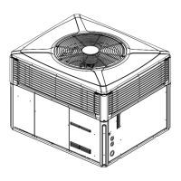
To install the unit at ground level: Place the unit on a pad the size of the unit or larger. The unit must be mounted level.

Ductwork Installation

Electrical Wiring

Starting the Unit

Pre-Start Quick Checklist

Review installation steps, clearances, ductwork, condensate line, filters, wiring, grounding, thermostat, and system checks.

Starting the Unit In the Cooling Mode

To start the unit in cooling, set thermostat to COOL and below room temperature. Outdoor fan, compressor, and evaporator fan will operate.

Starting the Unit in the Heating Mode

To start in heating, set thermostat to HEAT and above room temperature. Place fan switch in AUTO or ON positions.

Sequence Of Operation

Demand Defrost Operation

Control measures outdoor coil/ambient temp difference to determine defrost need. Unit enters cooling mode to defrost outdoor coil.

Final Installation Checklist

Maintenance

DEFROST CONTROL

PROCEDURE FOR TESTING SENSORS

Measure sensor resistance at various temperatures to verify correct operation. Compare measured values to the provided chart.

FAULT DETECTION

Indicates fault conditions via flashing light on defrost control. Normal is one flash per second.

DEFROST CONTROL CHECKOUT

Checks normal operation indicators: LED flashing, 24V AC readings between terminals, and defrost initiation via FRC_DFT.

Defrost Control Troubleshooting

SYMPTOMS

Lists common symptoms related to defrost control operation and their potential causes or checks.

Defrost Control Troubleshooting Continued

SYMPTOMS (Continued)

Details further symptoms for defrost control, covering timing, fan operation, and compressor issues.

Base Limited Warranty

Related product manuals