EasyManua.ls Logo

Trane A4AC3030A1000C User Manual

Trane A4AC3030A1000C
32 pages
To Next Page IconTo Next Page
Page #1 background imageLoading...
Page #1 background image
Installers Guide
April 2021
88-A4AC3001-1G-EN
SAFETY WARNING
Only qualified personnel should install and service the equipment. The installation, starting up, and servicing of heating, ventilating,
and air-conditioning equipment can be hazardous and requires specific knowledge and training. Improperly installed, adjusted or
altered equipment by an unqualified person could result in death or serious injury. When working on the equipment, observe all pre-
cautions in the literature and on the tags, stickers, and labels that are attached to the equipment.
Models
A4AC3018B1000B
A4AC3023A1000B
A4AC3024A1000B
A4AC3029A1000B
A4AC3030A1000C
A4AC3036A1000B
A4AC3042A1000B
A4AC3043A1000B
A4AC3048B1000B
A4AC3060A1000B
Note: “Graphics in this document are for representation only.
Actual model may differ in appearance.”
Condensing Units
Question and Answer IconNeed help?

Do you have a question about the Trane A4AC3030A1000C and is the answer not in the manual?

Trane A4AC3030A1000C Specifications

General IconGeneral
ModelA4AC3030A1000C
TypeAir Conditioner
Cooling Capacity2.5 tons
StagesSingle Stage
RefrigerantR-410A
Voltage208/230V
Phase1
Hertz60 Hz
Maximum Overcurrent Protection25 amps
Sound Level (Outdoor Unit)76 dB
Weight (Outdoor Unit)220 lbs
Cooling Capacity (BTU)30000 BTU
Compressor TypeScroll
HSPF RatingNot Applicable

Summary

Installer's Guide Overview

Condensing Unit Models

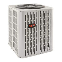
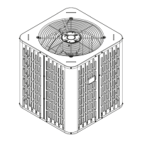
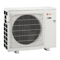
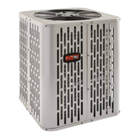
Lists the available outdoor unit models for the condensing units.

Installer Safety and Warnings

General Safety Precautions

Outlines critical safety warnings and precautions for installation and service personnel.

Unit Location and Piping Limits

Unit Dimensions and Weight Specifications

Provides physical dimensions and estimated weights for various outdoor unit models.

Refrigerant Piping System Limitations

Specifies maximum total length and vertical change limits for refrigerant lines.

Optimal Unit Placement and Climate Considerations

Suggested Locations for Best Reliability

Details clearance, noise, and airflow requirements for optimal unit placement.

Cold Climate Installation Guidelines

Provides guidance for installing units in areas prone to snow and freezing temperatures.

Unit Preparation and Setting Procedures

Unit Preparation and Damage Check

Instructions for checking the unit for damage and reporting issues before installation.

Unit Installation and Pad Requirements

Pad Installation Guidelines

Recommendations for properly installing the unit on a support pad.

Refrigerant Line Specifications

Line Size and Valve Connection Details

Details line sizes and service valve connections for different rated line sizes.

Refrigerant Charge and Line Handling

Factory Charge and System Capacity

Explains the factory refrigerant charge for the outdoor condensing unit.

Required Refrigerant Line Length Calculation

Instructions for determining the necessary refrigerant line length and lift.

Proper Refrigerant Line Insulation

Emphasizes the importance of insulating the vapor line and preventing contact.

Refrigerant Line Routing and Reuse

Reuse of Existing Refrigerant Lines

Precautions and guidelines for using existing refrigerant lines in retrofit applications.

Refrigerant Line Routing Best Practices

Refrigerant Line Routing Precautions

Guidance to prevent noise transmission and ensure proper routing of refrigerant lines.

Refrigerant Line Brazing Process

Brazing Refrigerant Lines

Step-by-step instructions for preparing and brazing refrigerant lines.

Refrigerant Line Leak Detection

Leak Check Procedure

Procedure for checking refrigerant lines and coils for leaks using dry nitrogen.

System Evacuation and Service Valve Operation

Evacuating Refrigerant Lines and Coil

Steps for evacuating refrigerant lines and indoor coil to a specific micron level.

Service Valve Procedures

Open the Gas Service Valve

Instructions on how to properly open the gas service valve.

Service Valve Operation and Low Voltage Wiring

Open the Liquid Service Valve

Safety warning and steps to safely open the liquid service valve.

Low Voltage Electrical Requirements

Low Voltage Maximum Wire Lengths

Table specifying maximum lengths for low voltage wiring based on wire gauge.

Low Voltage Electrical Connections

Low Voltage Hook-up Diagrams

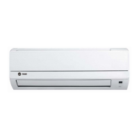
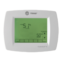
Wiring diagrams for connecting thermostats, air handlers, and outdoor units.

High Voltage Electrical Safety and Connections

High Voltage Power Supply Requirements

Safety warning and requirements for connecting the high voltage power supply.

High Voltage Disconnect Switch Installation

Recommendation to install a separate disconnect switch for high voltage connections.

High Voltage Grounding Procedures

Requirements for properly grounding the outdoor unit according to codes.

System Start-Up Procedure

Performing System Start-Up

Step-by-step instructions for powering up and starting the installed system.

System Charge Adjustment Methods

Temperature Measurements for Charging

Guidelines for measuring outdoor and indoor temperatures relevant to system charging.

Subcooling Charging (Outdoor Temp > 55°F)

Procedure for subcooling charging when outdoor ambient is above 55°F.

System Charge Adjustment Methods

Superheat Charging (Fixed Orifice)

Table to determine superheat for systems with fixed orifice metering devices.

System Charge Adjustment Methods

Subcooling Charging (Outdoor Temp < 55°F)

Recommended method for charging below 55°F outdoor temperature using weigh-in.

Final System Checks and Procedures

Operational and Checkout Procedures

Final inspection and checkout list to ensure proper system operation and safety.

Troubleshooting: Compressor Start Issues

Compressor Start-Up Troubleshooting Flowchart

Troubleshooting flowchart for diagnosing issues when the compressor fails to start.

Troubleshooting: Compressor Operation Issues

Compressor Not Running Troubleshooting Flowchart

Troubleshooting flowchart for diagnosing issues when the compressor is not running.

Troubleshooting: System Fault Diagnosis

System Faults and Cause Identification

A comprehensive guide to diagnosing system faults and their causes.

Refrigerant Circuit Schematics

Refrigerant Circuit Diagrams by Unit Size

Schematic diagrams illustrating refrigerant flow for various ton unit sizes.

Related product manuals