Do you have a question about the Trane ACONT900AC43UA and is the answer not in the manual?
Failure to follow warnings could result in injury, damage, or death.
Bodily injury from high voltage, fans, and combustible gas.
Disconnect power before removing blower door.
Failure to follow instructions could result in poisoning or death.
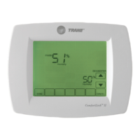
Steps and considerations for installing the Comfort Control, including location and sub-base.
Accessing and using the Installer Setup menu to customize installations.
Guide to operating the Comfort Control, including system and fan settings.
Features specific to heat pump operation, including lockout temperatures and defrost.
Information on the Charge Assist feature for system commissioning.
Operation of heat pump in cooling mode, including SOV energization.
Operation of heat pump in heating mode, including SOV de-energization.
How the system detects and clears frost or ice buildup on the outdoor coil.
Process of initiating a defrost cycle, including fan and auxiliary heat operation.
How the system terminates a defrost cycle based on coil temperature or time override.
Process of initiating defrost from first stage heating.
Process of terminating defrost to first stage heating.
Process of initiating defrost from second stage heating.
Process of terminating defrost to second stage heating.
High pressure cut-off control logic for all stages of operation.
Low pressure cut-off control logic for all stages of operation.
Low pressure cut-off logic specifically for cooling mode.
Capability of the control board to detect and report sensor faults and loss of control voltage.
Information on demand defrost cycle for heat pump models.
Advanced charging capability called Charge Assist.
Initiating a learning routine defrost cycle after system power up.
Common issues and fault indicators for the EEV control board.
Detailed steps for troubleshooting EEV issues in heating and cooling modes.
Testing the EEV's ability to drive closed and its effect on suction pressure.
Testing the EEV's ability to drive open and its effect on superheat.
Flowchart for diagnosing EEV issues based on system conditions.
Introduction to the suction line temperature sensor and its function.
Introduction to the suction line pressure transducer and its connection.
Introduction to the liquid line temperature sensor and its properties.
Method to test voltage across the liquid line temperature sensor.
Steps to measure the resistance of the liquid line sensor.
Introduction to the liquid line pressure transducer and its testing method.
Procedure for testing the liquid line pressure transducer.
Troubleshooting steps when the sump heater does not energize.
Troubleshooting steps when the sump heater fails to turn off during compressor operation.
Procedure to check for a plugged filter drier using temperature difference.
Checking the reversing valve coil for voltage and magnetic pull.
Checking the reversing valve in cooling mode.
Checking the reversing valve in heating mode, including forced defrost.
Guide for using the BAYCAKT001AA Charge Assist Tool.
Steps for connecting the Charge Assist tool to the unit.
Procedure for using Charge Assist with a communicating Comfort Control.
Steps to enter and use Charge Assist mode.
Procedure for systems using a non-communicating 24VAC control.
Troubleshooting common Charge Assist control issues.
Steps to troubleshoot the Charge Assist control based on LED flash codes.
Details on the air handler control board components and features.
Explanation of the Fault LED indications for detecting faults.
Detailed operational sequences for the air handler in various modes.
Checklist for troubleshooting communication issues.
Routine for learning inducer motor speed for optimal ventilation.
Learning routine for pressure switches PS-1 and PS-2.
Learning routine for high heat inducer motor speed.
Procedures for recovering alert codes displayed by the furnace control.
Operational sequences for three-stage gas furnaces.
Routine for learning the induced draft blower speed for the first stage.
Process of the IFC ramping up the vent motor to determine operating speed.
Adaptive learning routine for the second stage heat operation.
Procedures for testing pressure switches.
Procedure for measuring and adjusting manifold gas pressure for 80% furnaces.
Steps to adjust the manifold outlet pressure.
Procedure for measuring and adjusting manifold gas pressure for modulating furnaces.
Procedure for measuring and adjusting manifold gas pressure for three-stage furnaces.
Method to set manifold pressure using contingency mode for three-stage furnaces.
Procedures for checking gas valve solenoids.
Steps to check the gas valve solenoid.
Description of the ignitor learning routine.
Steps involved in the ignitor learning process.
Minimum DC microampere requirement for flame current detection.
Common causes for low flame current, such as dirty flame rod or poor ground.
Procedure to measure flame current using a digital multimeter.
Troubleshooting steps when furnace locks out due to flame current issues.
Steps to check switch continuity using an ohmmeter.
Steps to check switch voltage using a voltmeter.
Common reasons for flame roll-out trips.
Test to determine if the serial port variable speed blower motor is functioning.
Detailed test procedure for the indoor serial port variable speed blower motor.
Steps for troubleshooting the main limit switch.
Procedures to test the main limit switch operation.
Steps to perform an electrical check of the main limit switch.
Place meter leads across main limit electrical terminals.
Interpret zero volt reading as a closed switch.
Interpret 24-volt reading as an open switch.
Replace switch if it remains open below the set point.
Reasons for the main limit switch opening during operation.
A guide to understanding alert codes for communicating gas furnaces.
| Brand | Trane |
|---|---|
| Model | ACONT900AC43UA |
| Category | Air Conditioner |
| Language | English |