GF - D 4
Gas Valves
Modulating Furnace Manifold Gas Pressure
Measurement & Adjustments
Note: In Contingency Mode
Stage 1 = 40% (low) heat,
(120000 BTUH only = 45%)
Stage 2 = 100% (high) heat
The user interface must be set to Communicating
Mode [COMM]. Manifold pressure can not be set
in 24 Volt Mode [24VAC].
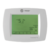
Step 3
Apply 115 VAC power to the furnace. The furnace User
Interface will display WAIT, and then the display will
change to CNTNGNCY MODE STG 1 50%. (Figure
9)
Step 1
Set up the furnace in the contingency mode of
operation at the User Interface for the Stage 1 low
heat with a 50% duty cycle. (Figure 7)
Figure 8
Figure 9
Setting Manifold Pressure
Using Contingency Mode
Step 12
Turn off all electrical power to the system.
Step 13
Remove the manometer and tubing and tighten the
pressure tap screws.
Step 14
Using a leak detection solution of soap suds, check
for leaks at the pressure outlet boss and pressure tap
test screw.
Step 15
Turn on system power and check operation of the
unit.
Step 2
Remove 115 VAC power from the furnace. Do not
repower the furnace until the Green LED on the inducer
motor drive board goes out. (Figure 8)
Figure 7
Note: Condensate trap must be primed before
gas valve manifold pressures are set.
 Loading...