Home
Trane
Heat Pump
A4AC3030D
Page 29 (Section 17. Wiring Diagrams)
Trane A4AC3030D - Section 17. Wiring Diagrams
44 pages
Manual
Save Page as PDF
To Next Page
To Next Page
To Previous Page
To Previous Page
Loading...
88-A4A
C3001-1J-EN
29
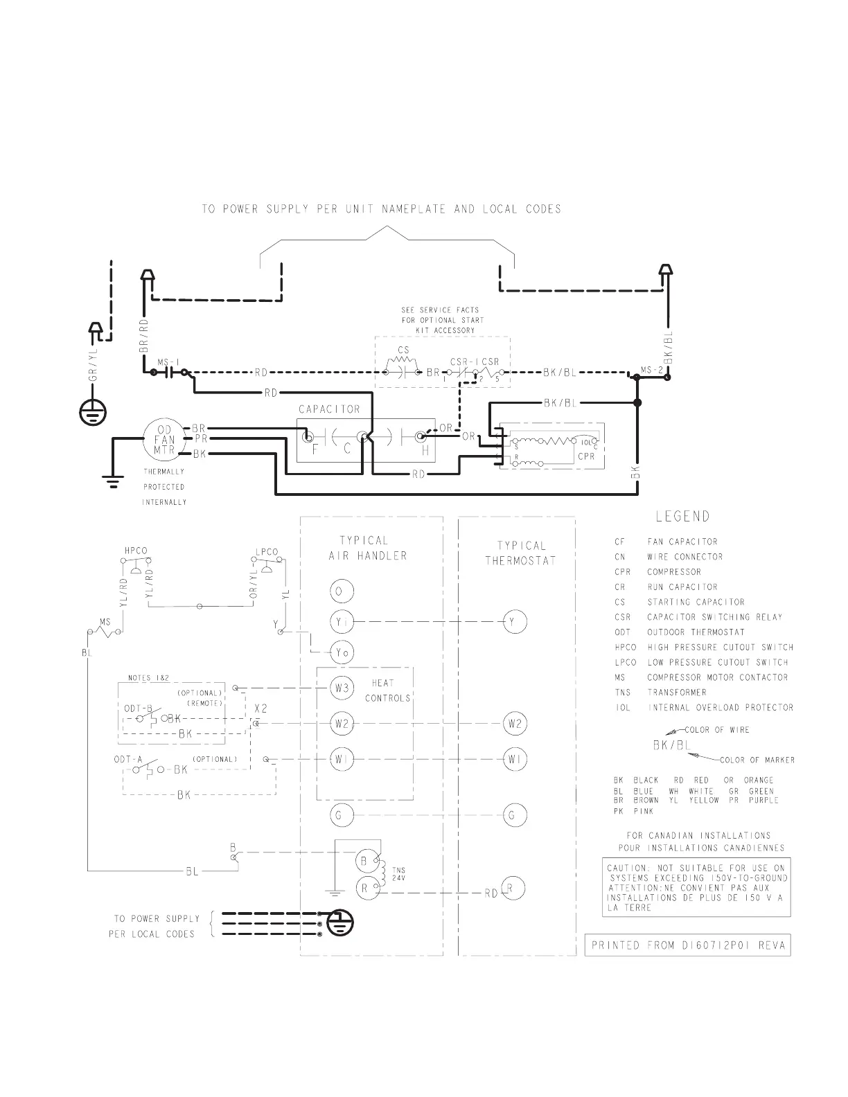
Section 17. Wiring Diagrams
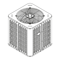
018D, 023D, 024D, 030D, 035D, 036D, 042D & 048D Models
018A, 023A, 024A, 029A, 036A, 042A, 043A & 048B Models
28
30
Table of Contents
Main Page
Section 1. Safety
2
Table of Contents
3
Section 2. Unit Location Considerations
4
Section 3. Unit Preparation
6
Section 4. Setting the Unit
6
Section 5. Refrigerant Line Considerations
7
Section 6. Refrigerant Line Routing
9
Section 7. Refrigerant Line Brazing
10
Section 8. Refrigerant Line Leak Check
12
Section 9. Evacuation
13
Section 10. Service Valves
13
Section 11. Electrical - Low Voltage
14
Section 12. Electrical - High Voltage
16
Section 13. Start up
17
Section 14. System Charge Adjustment (Systems Can be Rated with TXV, EEV or Piston)
18
Section 15. Checkout Procedures
24
Section 16. Refrigerant Circuits
25
Section 17. Wiring Diagrams
29
Section 18. Pressure Curves
35
Related product manuals
Trane A4AC3030A1000A
32 pages
Trane A4AC3036A1000A
32 pages
Trane A4AC3029A
44 pages
Trane A4AC3018A
32 pages
Trane A4AC3018D
44 pages
Trane A4AC3018A1000A
32 pages
Trane A4AC3042A1000A
32 pages
Trane A4AC3060A1000A
32 pages
Trane A4AC3024A1000A
32 pages
Trane A4AC3029A1000A
32 pages
Trane A4AC3043A1000A
32 pages
Trane A4AC3023A1000A
32 pages