Do you have a question about the Trane A4AC4018A1000A and is the answer not in the manual?
Table 2.1 lists unit dimensions and weight, essential for placement planning.
Details maximum refrigerant line length and vertical change for optimal system performance.
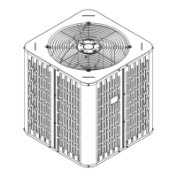
Provides guidance on unit placement to ensure adequate airflow and minimize noise.
First step in preparation involves checking the unit for any shipping damage.
Guidelines for installing the unit on a support pad, ensuring levelness and drainage.
Provides a table detailing line sizes and service valve connection sizes for various models.
Information on the factory refrigerant charge and how to verify proper system charge.
Instructions to determine required line length and lift for system configuration.
Emphasizes the importance of insulating the vapor line and preventing contact.
Precautions for using existing refrigerant lines in retrofit applications.
Key precautions for routing refrigerant lines to prevent noise and ensure proper installation.
Step-by-step instructions for brazing refrigerant lines to service valves.
Procedure for pressurizing lines with nitrogen and checking for leaks using soapy solution.
Instructions on how to evacuate the system to a specific micron level for proper operation.
Steps for safely opening the gas service valve to the fully open position.
Detailed procedure and warning for opening the liquid line service valve.
Table specifying maximum wire lengths for low voltage wiring based on gauge size.
Wiring diagrams for connecting thermostats, air handlers, and outdoor units for Heat Pump and AC systems.
Information on high voltage power supply requirements and compliance with codes.
Recommendation to install a separate disconnect switch at the outdoor unit.
Requirement to ground the outdoor unit according to national, state, and local codes.
Step-by-step guide for powering up the system after installation is complete.
Instructions for measuring outdoor and indoor temperatures for system charging.
Method for subcooling charging in cooling mode for systems with TXV or EEV.
List of procedures to perform after installation to ensure proper operation and safety.
Flowchart for diagnosing and resolving common compressor start-up issues.
Diagram illustrating refrigerant flow and components for 1 1/2-Ton units.
Diagram of refrigerant flow and components for 2, 2 1/2, and 3-Ton units.
Diagram of refrigerant flow and components for 3 1/2 and 4-Ton units.
Diagram illustrating refrigerant flow and components for 5-Ton units.
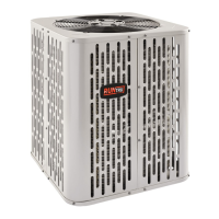
This document is an Installer's Guide for Trane Condensing Units, providing comprehensive instructions for installation, startup, and troubleshooting. It emphasizes compliance with national, state, and local codes throughout all installation phases.
The guide details the proper procedures for installing and servicing Trane Condensing Units, which are integral components of heating, ventilating, and air-conditioning (HVAC) systems. It covers everything from initial unit preparation and placement to refrigerant line installation, electrical connections, system startup, and charge adjustment. The document is intended for qualified personnel due to the hazardous nature of HVAC equipment installation and servicing. It highlights the importance of using approved matched indoor and outdoor systems to ensure maximum efficiency, optimum performance, and overall system reliability.