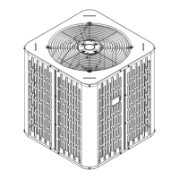
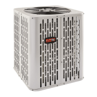
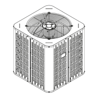
This document is an Installer's Guide for Condensing Units, specifically covering models A4AC4018B1000B, A4AC4023A1000B, A4AC4024A1000B, A4AC4030A1000C, A4AC4036A1000B, A4AC4042A1000B, A4AC4048A1000B, and A4AC4060A1000B. It provides comprehensive instructions for the safe and proper installation, startup, and servicing of these outdoor air conditioning units.
The guide emphasizes safety throughout, stating that only qualified personnel with adequate electrical and mechanical experience should install and service the equipment. It highlights that improper installation or servicing by unqualified individuals can lead to death or serious injury. All installation phases must comply with national, state, and local codes.
Function Description:
The condensing units are designed for residential air conditioning applications, working in conjunction with indoor evaporator coils to create comfortable and energy-efficient indoor environments. They utilize R-410A refrigerant, which operates at higher pressures than R-22, necessitating the use of R-410A approved service equipment. The units are factory charged with the system charge required for the outdoor condensing unit, ten feet of tested connecting line, and the smallest rated indoor evaporative coil match.
Important Technical Specifications:
- Refrigerant: R-410A.
- Compressor Oil: POE oil.
- Refrigerant Line Limits:
- Maximum length of refrigerant lines: 60 feet.
- Maximum vertical change: 60 feet.
- For line lengths exceeding 60 feet, refer to specific Refrigerant Piping Application Guides.
- Electrical - Low Voltage Maximum Wire Length (24 VOLTS):
- 18 AWG: 150 Ft.
- 16 AWG: 225 Ft.
- 14 AWG: 300 Ft.
- Unit Dimensions and Weight (H x D x W in / Weight lb - estimated):
- A4AC4018B: 28.6 x 23.6 x 23.6 / 130
- A4AC4023A: 32.6 x 23.6 x 23.6 / 130
- A4AC4024A: 28.6 x 25.6 x 25.6 / 134
- A4AC4030A: 28.6 x 29.8 x 29.8 / 163
- A4AC4036A: 32.6 x 29.8 x 29.8 / 161
- A4AC4042A: 28.6 x 34.3 x 34.3 / 159
- A4AC4048A: 28.6 x 34.3 x 34.3 / 159
- A4AC4060A: 36.6 x 34.3 x 34.3 / 220
- Refrigerant Line and Service Valve Connection Sizes (Vapor Line / Liquid Line):
- A4AC4018B to A4AC4036A: 3/4" / 3/8"
- A4AC4042A to A4AC4060A: 7/8" / 3/8"
- Refrigerant Adders for Additional Line Length (Suction Line / Liquid Line):
- 3/4" / 3/8": 3 oz (20 ft), 9 oz (30 ft), 15 oz (40 ft), 21 oz (50 ft), 27 oz (60 ft)
- 7/8" / 3/8": 3 oz (20 ft), 9 oz (30 ft), 16 oz (40 ft), 22 oz (50 ft), 28 oz (60 ft)
Usage Features:
- Unit Location:
- Top discharge area must be unrestricted for at least five feet above the unit.
- Three feet clearance required in front of the control box (access panels) and any other side needing service.
- Minimum 12 inches from any wall or surrounding shrubbery for adequate airflow.
- Avoid locating near bedrooms due to operational sounds.
- Ensure the roof can support the unit's weight if mounted on a roof, and use isolation to prevent sound/vibration transmission.
- Pad Installation:
- Pad should be at least 1 inch larger than the unit on all sides, separate from any structure, level, and high enough for drainage.
- Refrigerant Line Routing:
- Use isolation hangers when fastening lines to joists, rafters, or framing to prevent vibration transmission.
- Insulate and isolate lines running through walls or sills.
- Isolate lines from all ductwork and minimize 90-degree turns.
- System Start-Up:
- Ensure all installation steps (sections 7-12) are complete.
- Set system thermostat to OFF.
- Turn on disconnect(s) to apply power.
- Wait one hour before starting if a compressor crankcase heater accessory is used and ambient temperature is below 70°F.
- Set system thermostat to ON.
- System Charge Adjustment:
- For piston metering devices, refer to the Superheat charging method.
- For TXV or EEV indoor metering devices, refer to the Subcool charging method.
- Subcooling is the recommended charging method above 55°F ambient outdoor temperature.
- Indoor temperature should be kept between 70°F and 80°F for best results.
- Allow the system to operate for a minimum of 20 minutes to stabilize before making accurate charge measurements.
Maintenance Features:
- Refrigerant Handling:
- R-410A systems use POE oil, which readily absorbs moisture; keep the system sealed whenever possible.
- If the system has been open to the atmosphere for more than 4 hours, the compressor oil must be replaced.
- Never break a vacuum with air and always change driers when opening the system for component replacement.
- Use only R-410A refrigerant and approved POE compressor oil.
- Brazing:
- Remove caps/plugs, debur pipe ends, and clean tubing surfaces.
- Remove pressure tap cap and valve cores from service valves before brazing.
- Purge lines and indoor coil with dry nitrogen during brazing.
- Wrap a wet rag around the valve body to prevent heat damage during brazing; do not remove until brazing is complete.
- Install drier in the liquid line.
- Replace valve cores after valves have cooled.
- Leak Check:
- Pressurize lines and evaporator coil to 150 PSIG with dry nitrogen.
- Check for leaks with soapy solution at all brazed locations.
- Repair any leaks before proceeding.
- Evacuation:
- Evacuate until the micron gauge reads no higher than 350 microns.
- Evacuation is complete if the micron gauge does not rise above 500 microns in one minute after closing the valve to the vacuum pump.
- Service Valves:
- Open the gas service valve 1/4 turn counterclockwise to the fully open position.
- Open the liquid service valve by backing out the stem counterclockwise until it just touches the rolled edge (approx. five turns).
- Replace valve stem caps and tighten finger tight plus an additional 1/6 turn to prevent leaks.
- Checkout Procedures:
- Perform a final unit inspection to ensure factory tubing has not shifted and wiring connections are tight.
- Verify proper insulation of suction lines and fittings.
- Ensure the indoor coil drain line drains freely.
- Confirm supply registers and return grilles are open and unobstructed.
- Verify a return air filter is installed.
- Check the correct airflow setting for the indoor blower motor.
- Operate the complete system in each mode to ensure safe operation.
- Troubleshooting:
- The guide includes flowcharts for diagnosing common issues like "Compressor fails to start" and "Compressor won't run."
- It also provides a "System Faults" table listing primary and secondary causes for various refrigerant circuit, electrical, and defrost problems.