6
18-GF15D1-1B-EN
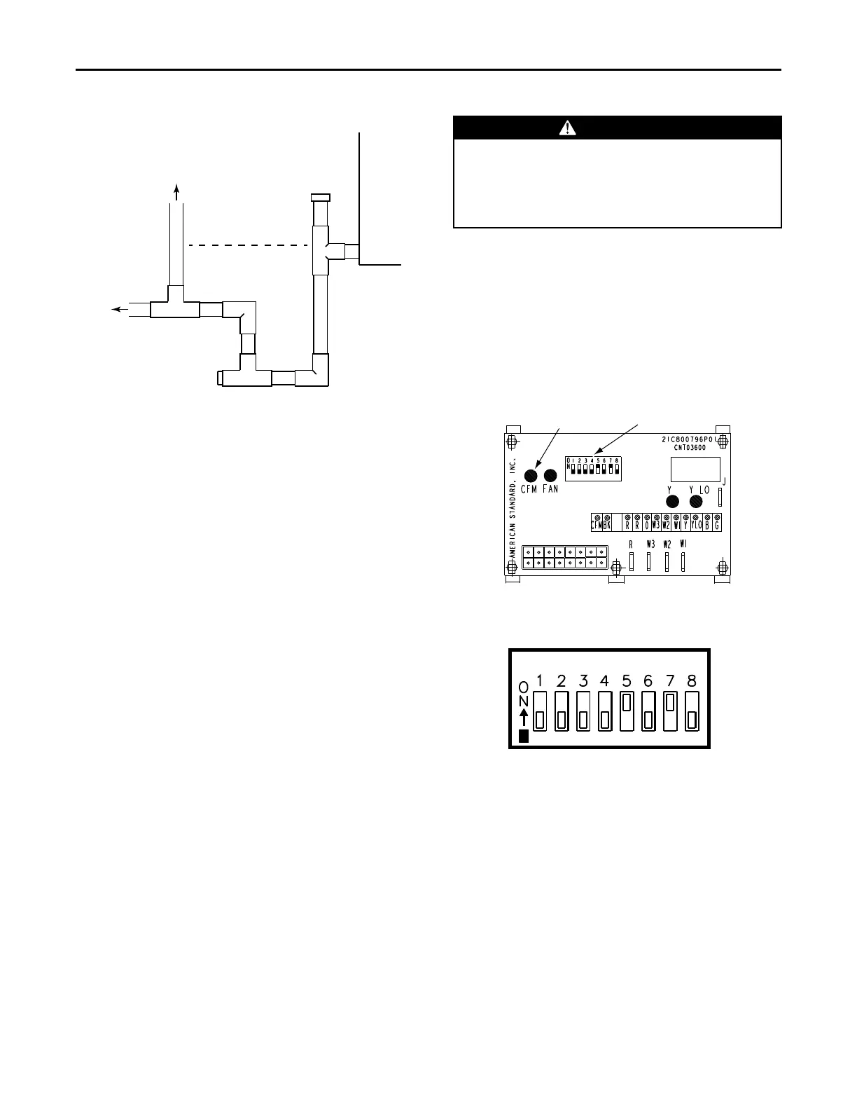
To Drain
Vent
-This vent pipe MUST
terminate above the
dotted line
Cleanout
(with Cap)
Cleanout
(Plug)
Insulate the primary drain line to prevent sweating
where dew point temperatures may be met.
(Insulation is optional depending on climate and
application needs.)
5. RReeffrriiggeerraanntt PPiippiinngg
Refrigerant piping external to the unit shall be sized
in accordance with the instructions of the
manufacturer of the outdoor equipment.
6. MMeetteerriinngg DDeevviiccee
All units are shipped and installed with an
internally-checked, non-bleed TXV designed for air
conditioning or heat pump operation. Some
outdoor models may require a start assist kit. See
outdoor unit for more information.
7. MMuullttii--SSppeeeedd BBlloowweerrss ((AA44AAHH55EE**))
This unit is supplied with a multi-speed motor with
a direct drive blower wheel which can obtain
various air flows. The unit is shipped with factory
set cooling and heating speed taps. Airflow
performance tables are available for additional
speed taps. Disconnect all power to the unit before
making any adjustments to the motor speed taps.
Be sure to check the air flow and the temperature
drop across the evaporator coil to ensure sufficient
air flow.
8. VVaarriiaabbllee--SSppeeeedd BBlloowweerrss ((AA44AAHH55VV**))
This unit is supplied with a variable speed motor
with a direct drive blower wheel which can obtain
various air flows. The unit is shipped with factory
set cooling and heating air flows. Performance
tables are available for additional airflow settings.
Disconnect all power to the unit before making any
adjustments to the airflow settings. Be sure to
check the air flow and the temperature drop across
the evaporator coil to ensure sufficient air flow.
9. AAiirrffllooww AAddjjuussttmmeenntt
CCAAUUTTIIOONN
EEQQUUIIPPMMEENNTT DDAAMMAAGGEE!!
FFaaiilluurree ttoo ffoollllooww tthhiiss pprroocceedduurree mmaayy rreessuulltt iinn
eeqquuiippmmeenntt ddaammaaggee..
DDiissccoonnnneecctt ppoowweerr ttoo tthhee aaiirr hhaannddlleerr bbeeffoorree
cchhaannggiinngg ddiipp sswwiittcchh ppoossiittiioonnss..
Blower speed changes are made on the ECM Fan
Control. The ECM Fan Control controls the variable
speed motor.
There is a bank of 8 dip switches. The dip switches
work in pairs to match the airflow for the outdoor
unit size (tons). cooling airflow adjustment, Fan off-
delay options, and heating airflow adjustment.
Figure 1. ECM Fan Control
CFM
SELECTION
LIGHT
DIP
SWITCHES
Figure 2. Dip Switches
DIP SWITCHES (TYPICAL SETTINGS)
COOLING
HEATING
AIRFLOW
FAN OFF
DELAY
AUXILARY
HEAT SPEEDS
If the airflow needs to be increased or decreased,
see the Airflow Label on the air handler or Blower
Performance Table.
Be sure to set the correct airflow for cooling and
heating.
Switches 1–4 Cooling Airflow
Switches 5–6 Fan Off Delay Options
Switches 7–8 Auxiliary Heat
IInnddoooorr BBlloowweerr TTiimmiinngg
IImmppoorrttaanntt:: Leave dip switches 5 and 6 in the “as-
shipped” positions during system start-
up and check out. Afterwards, adjust as
desired.
IInnssttaallllaattiioonn IInnssttrruuccttiioonnss