EasyManua.ls Logo

Trane A4AH5E19A1B30A User Manual

Trane A4AH5E19A1B30A
32 pages
To Next Page IconTo Next Page
Page #1 background imageLoading...
Page #1 background image
SSAAFFEETTYY WWAARRNNIINNGG
Only qualified personnel should install and service the equipment. The installation, starting up, and servicing of heating, ventilating, and air-conditioning
equipment can be hazardous and requires specific knowledge and training. Improperly installed, adjusted or altered equipment by an unqualified person
could result in death or serious injury. When working on the equipment, observe all precautions in the literature and on the tags, stickers, and labels that
are attached to the equipment.
October 2022 1188--GGFF1155DD11--11BB--EENN
Convertible Air Handlers
1–1/2 5 Ton
A4AH5E19A1B30A
A4AH5V24A1B30A
A4AH5V30A1B30A
A4AH5E31A1B30A
A4AH5V36A1C30A
A4AH5V42A1C30A
A4AH5E43A1C30A
A4AH5V48A1C30A
A4AH5E49A1C30A
A4AH5V60A1C30A
A4AH5E61A1C30A
The A4AH5 series air handler is designed for installation in a closet,
utility room, alcove, basement, crawlspace or attic. These versatile
units are applicable to air conditioning and heat pump
applications. Several models are available to meet the specific
requirements of the outdoor equipment. Field installed electric
resistance heaters are available.
Installer’s Guide
Question and Answer IconNeed help?

Do you have a question about the Trane A4AH5E19A1B30A and is the answer not in the manual?

Trane A4AH5E19A1B30A Specifications

General IconGeneral
SEER16
StagesSingle
Voltage208/230V
Nominal Airflow600 CFM
Phase1
Motor TypePSC
Depth21 inches
Cooling Capacity18, 000 BTU/hr

Summary

Safety Information

Safety Warnings and Precautions

Critical safety warnings and precautions for installation and servicing.

Product Features Overview

Lists standard and optional features of the air handler units.

Installation Guide

Initial Installation Steps

Covers unpacking, location, ducting, and condensate drain setup.

Connection and Adjustment Steps

Details refrigerant piping, blower adjustment, and airflow configuration.

Wiring, Thermostat, and Final Setup

Covers electrical wiring, thermostat, air filter, and operational sequence.

Post-Installation Checks and Maintenance

Outlines operational checks, checkout procedures, and maintenance.

Technical Data

Field Wiring Diagrams

Diagrams for field wiring the air handler to thermostat and outdoor unit.

Electrical Data and Schematics

Provides electrical schematics and data for the air handler units.

Performance and Airflow Data

Presents air flow performance and electrical data for various models.

Minimum Airflow CFM

Provides minimum airflow requirements for various heater and speed tap combinations.

Outline Drawing and Dimensions

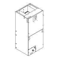
Provides dimensional drawings and clearance information for the air handler unit.

Heater Pressure Drop and Subcooling

Details pressure drop across heaters and subcooling adjustment procedures.

Conversion and Checkout

Coil Conversion Instructions

Step-by-step instructions for converting the air handler coil for different configurations.

Downflow Coil Conversion

Step-by-step guide for converting the coil for downflow installation.

Horizontal Right Coil Conversion

Step-by-step guide for converting the coil for horizontal right installation.

Checkout Procedures

A final checklist to ensure proper system installation and operation.

Related product manuals