EasyManua.ls Logo

Trane A4AH5E43A1C30A User Manual

Trane A4AH5E43A1C30A
32 pages
To Next Page IconTo Next Page
Page #1 background imageLoading...
Page #1 background image
SSAAFFEETTYY WWAARRNNIINNGG
Only qualified personnel should install and service the equipment. The installation, starting up, and servicing of heating, ventilating, and air-conditioning
equipment can be hazardous and requires specific knowledge and training. Improperly installed, adjusted or altered equipment by an unqualified person
could result in death or serious injury. When working on the equipment, observe all precautions in the literature and on the tags, stickers, and labels that
are attached to the equipment.
October 2022 1188--GGFF1155DD11--11BB--EENN
Convertible Air Handlers
1–1/2 5 Ton
A4AH5E19A1B30A
A4AH5V24A1B30A
A4AH5V30A1B30A
A4AH5E31A1B30A
A4AH5V36A1C30A
A4AH5V42A1C30A
A4AH5E43A1C30A
A4AH5V48A1C30A
A4AH5E49A1C30A
A4AH5V60A1C30A
A4AH5E61A1C30A
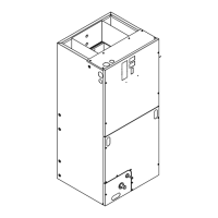
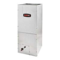
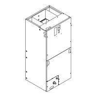
The A4AH5 series air handler is designed for installation in a closet,
utility room, alcove, basement, crawlspace or attic. These versatile
units are applicable to air conditioning and heat pump
applications. Several models are available to meet the specific
requirements of the outdoor equipment. Field installed electric
resistance heaters are available.
Installer’s Guide
Question and Answer IconNeed help?

Do you have a question about the Trane A4AH5E43A1C30A and is the answer not in the manual?

Trane A4AH5E43A1C30A Specifications

General IconGeneral
BrandTrane
ModelA4AH5E43A1C30A
CategoryAir Handlers
LanguageEnglish

Summary

Convertible Air Handler Introduction

Installer Safety Warning

General safety precautions for qualified personnel installing the equipment.

Safety Warnings and Precautions

Hazardous Voltage Warning

Warning about high voltage and required lockout/tagout procedures.

Grounding Requirement

Emphasizes the necessity of proper grounding for all parts.

Live Electrical Components Warning

Warning about working with live electrical components.

Pressurized Refrigerant Warning

Warning regarding high-pressure refrigerant and proper recovery.

Sharp Edge Hazard Caution

Caution about potential injury from sharp edges on equipment.

Hazardous Vapors Caution

Caution regarding corrosive conditions from certain chemicals.

Pressurized Coil Caution

Information about coil pressure and safe release procedures.

Appliance Usage Safety Hazard

Safety notice regarding appliance use by persons with reduced capabilities.

Additional Safety and Product Features

Child Safety Hazard

Warning to supervise children to ensure they do not play with the appliance.

Chemical Exposure Warning

Warning about chemical exposure, including lead, as per California P65.

Installation Instructions

Unpacking and Inspection

Procedure for unpacking the unit and inspecting for damage or discrepancies.

Unit Location Guidelines

Recommendations for centralizing the air handler location and minimum clearances.

Condensate Drain System

Instructions for installing and properly trapping the condensate drain.

Installation Procedures and Airflow

Airflow Adjustment and Controls

Details on adjusting airflow using dip switches and ECM fan control.

Wiring, Air Filter, and Thermostat

Wiring Guidelines

Instructions for field wiring, NEC compliance, and wire sizing.

Operation, Checkout, and Maintenance

Operational and Checkout Procedures

Steps to ensure proper performance after installation.

Field Wiring Diagrams

Heat Pump System Wiring

Diagram illustrating wiring connections for heat pump systems.

AC System Wiring

Diagram illustrating wiring connections for AC-only systems.

Field Wiring for Variable Speed Models

Single Stage Wiring (Cooling/HP)

Field wiring diagrams for single-stage cooling and heat pump systems.

Two Stage Wiring (Cooling/HP)

Field wiring diagrams for two-stage cooling and heat pump systems.

Electrical Schematic and Data

A4AH5E Electrical Schematic

Detailed electrical schematic for A4AH5E models.

Electrical Schematics for Variable Speed Models

A4AH5V Electrical Schematic

Detailed electrical schematic for A4AH5V variable speed models.

Coil Conversion Instructions

Downflow Conversion Steps

Detailed steps for converting the air handler for downflow installation.

Coil Conversion for Downflow and Horizontal Right

Downflow Conversion Steps (Continued)

Completion of downflow conversion steps and preparation for horizontal right.

Horizontal Right Conversion Steps

Initial steps for converting the air handler for horizontal right installation.

Horizontal Right Coil Conversion Details

Horizontal Right Coil Orientation

Adjusting coil orientation and drain pan for horizontal right installation.

Horizontal Right Water Diverter Brackets

Instructions for removing and reinstalling water diverter brackets for horizontal right.

Final Coil Conversion Steps

Downflow Relocation and Reassembly

Steps for relocating the drain pan and reassembling the coil in downflow.

Horizontal Right Reassembly

Steps for reassembling the coil and panels for horizontal right installation.

Checkout Procedures

Installation Checkout Checklist

A comprehensive checklist to confirm all installation requirements are met.

Related product manuals