© 2011 Trane
NOTICE: Since the manufacturer has a policy of continuous product and product data improvement, it reserves the right to change design and specifications without notice.
HyperionFieldReferenceDataTAM7
IMPORTANT --- This document contains a wiring diagram and service information. This is customer property and is to remain with this unit.
Please return to service information pack upon completion of work.
HAZARDOUS VOLTAGE - DISCONNECT POWER BEFORE SERVICING
WARNING:
For use with BAYEV or BAYW series heaters ONLY
SAFETY HAZARD! This information is intended for use
by individuals possessing adequate backgrounds of electrical and
mechanical experience. Any attempt to repair a central air condition-
ing product may result in personal injury and/or property damage.
The manufacture or seller cannot be responsible for the interpreta-
tion of this information, nor can it assume any liability in connection
with its use.
PRESSURIZED REFRIGERANT! SYSTEM CONTAINS
OIL AND REFRIGERANT UNDER HIGH PRESSURE. RECOVER
REFRIGERANT TO RELIEVE PRESSURE BEFORE OPENING THE
SYSTEM.
DO NOT USE NON-APPROVED REFRIGERANTS OR REFRIGERANT
SUBSTITUTES OR REFRIGERANT ADDITIVES.
LIVE ELECTRICAL COMPONENTS! During instal-
lation, testing, servicing, and troubleshooting of this product, it may
be necessary to work with live electrical components. Failure to fol-
low all electrical safety precautions when exposed to live electrical
components could result in death or serious injury.
Note: This unit is certified to UL 1995.
The interior cabinet wall meets the following:
- UL94-5VA Flame Class Listed
- UL723 Steiner Tunnel Listed for 25/50 Flame/
Smoke
- UL746C Listed for Exposure to Ultraviolet Light,
Water Exposure and Immersion
Table of Contents
Product Specifications. .................................................................................................... 2
Wiring Diagram. ............................................................................................................... 3
Sequence of Operation. ................................................................................................... 4
Control Layout - Refrigerant Dip Switches....................................................................... 7
Airflow Performance. ...................................................................................................... 10
Heater Attribute Data. .................................................................................................... 16
Control Layout - LEDs. ................................................................................................... 19
EEV Test Procedures. .................................................................................................... 24
EVC Thermal Resistance and Voltage Table. ................................................................ 25
Troubleshooting. ............................................................................................................ 26
* May be "A" or "T"
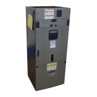
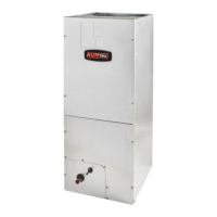
Air Handler - Convertible
Models: Series 7 Air Handlers 2-5 Ton
*AM7A0A24H21SA, *AM7A0B30H21SA
*AM7A0C36H31SA, *AM7A0C42H31SA
*AM7A0C48H41SA, *AM7A0C60H51SA


 Loading...