EasyManua.ls Logo

Trane AM7A0C36H31SA User Manual

Trane AM7A0C36H31SA
20 pages
To Next Page IconTo Next Page
Page #1 background imageLoading...
Page #1 background image
© 2011 Trane
NOTICE: Since the manufacturer has a policy of continuous product and product data improvement, it reserves the right to change design and specifications without notice.
IMPORTANT --- This document contains a wiring diagram and ser-
vice information. This is customer property and is to remain with
this unit. Please return to service information pack upon completion
of work.
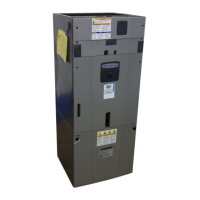
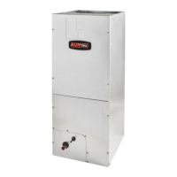
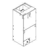
Air Handler - Convertible
Model: *AM7A0C36H31SA
* May be "A" or "T"
1 These Air Handlers are AHRI. certified with various Split System Air Conditioners
and Heat Pumps (AHRI STANDARD 210/240). Refer to the Split System Outdoor
Unit Product Data Guides for performance data.
2 3/4" Male Plastic Pipe (Ref.: ASTM 1785-76)
HAZARDOUS VOLTAGE - DISCONNECT POWER BEFORE SERVICING
WARNING:
Service Facts
For use with BAYEV series heaters ONLY
WARNING
!
SAFETY HAZARD! This information is intended for use
by individuals possessing adequate backgrounds of electrical and
mechanical experience. Any attempt to repair a central air condition-
ing product may result in personal injury and/or property damage.
The manufacture or seller cannot be responsible for the interpreta-
tion of this information, nor can it assume any liability in connection
with its use.
PRESSURIZED REFRIGERANT! SYSTEM CONTAINS
OIL AND REFRIGERANT UNDER HIGH PRESSURE. RECOVER
REFRIGERANT TO RELIEVE PRESSURE BEFORE OPENING THE
SYSTEM.
DO NOT USE NON-APPROVED REFRIGERANTS OR REFRIGERANT
SUBSTITUTES OR REFRIGERANT ADDITIVES.
WARNING
!
LIVE ELECTRICAL COMPONENTS! During instal-
lation, testing, servicing, and troubleshooting of this product, it may
be necessary to work with live electrical components. Failure to fol-
low all electrical safety precautions when exposed to live electrical
components could result in death or serious injury.
WARNING
!
Note: This unit is certified to UL 1995.
The interior cabinet wall meets the following:
- UL94-5VA Flame Class Listed
- UL723 Steiner Tunnel Listed for 25/50 Flame/
Smoke
- UL746C Listed for Exposure to Ultraviolet Light,
Water Exposure and Immersion
AM7A0C36H31-SF-1A
PRODUCT SPECIFICATIONS
MODEL *AM7A0C36H31SA
RATED VOLTS/PH/HZ. 208-230/1/60
RATINGS 1
See O.D. Specifications
INDOOR COIL — Type Plate Fin
Rows — F.P.I. 3 - 14
Face Area (sq. ft.) 5.50
Tube Size (in.) 3/8
Refrigerant Control EEV
Drain Conn. Size (in.) 2 3/4 NPT
DUCT CONNECTIONS
See Outline Drawing
INDOOR FAN — Type Centrifugal
Diameter-Width (In.) 11 X 10
No. Used 1
Drive - No. Speeds Direct - Variable
CFM vs. in. w.g. See Fan Performance Table
No. Motors — H.P. 1 - 1/2
Motor Speed RPM Variable ECM
Volts/Ph/Hz 208-230/1/60
F.L. Amps 3.0
FILTER
Filter Furnished? No
Type Recommended Throwaway
No.-Size-Thickness 1 - 22 X 20 - 1 in.
REFRIGERANT R-410A
Ref. Line Connections Brazed
Coupling or Conn. Size — in. Gas 7/8
Coupling or Conn. Size — in. Liq. 3/8
DIMENSIONS H x D x W
Crated (In.) 57.25 x 23.5 x 25.25
Uncrated 56.9 x 21.75 x 23.5
WEIGHT
Shipping (Lbs.) / Net (Lbs.) 157/146
Question and Answer IconNeed help?

Do you have a question about the Trane AM7A0C36H31SA and is the answer not in the manual?

Trane AM7A0C36H31SA Specifications

General IconGeneral
ModelAM7A0C36H31SA
TypeAir Handler
Airflow1, 200 CFM
RefrigerantR-410A
Nominal Airflow1, 200 CFM
Motor TypeECM
Voltage208/230V
Phase1
Cooling Capacity36, 000 BTU/h
Maximum External Static Pressure0.8 in. wg
Filter TypeStandard
Length21 inches

Summary

Product Specifications Summary

Key Unit and Coil Parameters

Details model, voltage, phase, frequency, coil type, and ratings.

Fan, Duct, and Refrigerant Info

Covers fan type, duct connections, refrigerant, and filter specifications.

Safety Warnings and Precautions

Electrical and Refrigerant Hazards

Alerts to hazardous voltage, live components, and pressurized refrigerant.

Service Personnel and Liability

Stresses qualified personnel and limits manufacturer liability.

Wiring Diagram

Diagram Legend and Components

Explains symbols and identifies main components in the wiring diagram.

Electrical Safety Notes

Includes warnings about hazardous voltage and conductor requirements.

Sequence of Operation

Abbreviations and Continuous Fan

Defines terms and describes continuous fan mode.

Heatpump OD Operation Modes

Details single and two-stage heating operations.

Cooling Operation Modes

Explains single and two-stage cooling operations.

Advanced Operational Modes

Cooling, Electric Heat, and Defrost

Covers cooling details, electric heat, and defrost sequences.

Optional Features and Protections

Details condensate switch, freeze protection, and blower delays.

Unit Testing, Diagnostics, and Adjustment

Test Mode and Fault Management

Entering test mode, reporting, and clearing faults.

Subcooling Adjustment Guidelines

Procedures for achieving target subcooling.

Control Layout and Identification

AFC and EVC Board Layouts

Identifies key components and connectors on control boards.

Refrigerant Switch Configuration

Setting the SW1 refrigerant switch on the EVC.

S1 Dip Switch Settings

Outdoor Unit Multiplier and Stages

Configures OD multiplier and system stages.

Compressor and System Type Settings

Sets compressor count and AC/HP type.

S2 Dip Switch Settings

CFM/Ton and Cool Off Delay

Sets CFM/Ton and cool off delay parameters.

Airflow Mode Selection

Chooses between Torque and Constant CFM airflow modes.

Airflow Performance Data

External Static Pressure Performance

Airflow and power data at various static pressures.

Minimum Heating Airflow Settings

Minimum heating CFM for model combinations.

Heater and Motor Specifications

Heater Attribute Data

Heater capacity, kW, BTUH, and circuit requirements.

Motor Vibration Distance (DIM 'A')

Specifies motor shaft face to belly band distance.

Control Panel Component Layout

AFC, Distribution Board, EVC Layouts

Identifies connectors, jumpers, and LEDs on control boards.

Airflow Control (AFC) Status and Faults

AFC Status and Fault LED Indicators

Explains AFC status and fault LED meanings.

AFC Fault Codes

Lists specific fault codes and their descriptions.

EVC Status and Fault Codes

EVC Status LED Indications

Explains EVC status LED meanings for different systems.

EVC Fault Code Descriptions

Lists specific fault codes and their descriptions for the EVC.

EHC Status and Fault Codes

EHC Status LED Indicators

Explains EHC status LED meanings for heater relays.

EHC Fault Code Descriptions

Lists specific fault codes and their descriptions for the EHC.

EEV Testing Procedures

EEV Sensor Identification

Locates the Vapor Line and Saturation Sensors.

Valve Close and Open Test

Procedures for testing EEV closing and opening functions.

Thermistor and Voltage Tables

Evap Saturation Sensor Data

Temperature, resistance, and voltage for Evap Saturation sensor.

Evap Gas Sensor Data

Temperature, resistance, and voltage for Evap Gas sensor.

Sensor Diagnostic Procedure

Voltage and Resistance Verification

Checks sensor connections, voltage, and resistance.

High Superheat Troubleshooting

Initial Checks and EEV Valve Tests

Verifies coils, line set, subcooling, and EEV valve functions.

System Operation and Temperature Analysis

Analyzes running conditions and temperature impacts on superheat.

Low Superheat Troubleshooting

Blower, Filter, and Coil Checks

Verifies blower operation, filter, coil, and wheel cleanliness.

EEV Valve and Coil Resistance Tests

Performs EEV valve tests and checks coil resistance.

Related product manuals