EasyManua.ls Logo

Trane A4HP4060A1000B - User Manual

Trane A4HP4060A1000B
28 pages
Print Icon
To Next Page IconTo Next Page
Loading...
Installers Guide
May 2022
88-A4HP4001-1E-EN
SAFETY WARNING
Only qualified personnel should install and service the equipment. The installation, starting up, and servicing of heating, ventilating,
and air-conditioning equipment can be hazardous and requires specific knowledge and training. Improperly installed, adjusted or
altered equipment by an unqualified person could result in death or serious injury. When working on the equipment, observe all pre-
cautions in the literature and on the tags, stickers, and labels that are attached to the equipment.
Models
A4HP4018D1000A A4HP4017A1000B
A4HP4024D1000A A4HP4018A1000B
A4HP4030D1000A A4HP4023A1000B
A4HP4036D1000A A4HP4024A1000B
A4HP4042D1000A A4HP4030A1000B
A4HP4048D1000A A4HP4036A1000B
A4HP4060D1000A A4HP4042A1000B
A4HP4048A1000B
A4HP4060A1000B
Note: “Graphics in this document are for representation only.
Actual model may differ in appearance.”
Heat Pumps
Question and Answer IconNeed help?

Do you have a question about the Trane A4HP4060A1000B and is the answer not in the manual?

Summary

Installers Guide Safety Warning

Safety

General Safety Precautions

Important warnings and cautions regarding installation, handling of refrigerants, and electrical safety.

Refrigerant Line Considerations

Refrigerant Line Brazing

Brazing Refrigerant Lines

Step-by-step procedure for properly brazing refrigerant lines, including preparation and purging.

Refrigerant Line Leak Check

Checking for Leaks

Procedure to pressurize lines with nitrogen and check for leaks using soapy solution.

Evacuation

Evacuating Lines and Coil

Steps to evacuate refrigerant lines and indoor coil to a specific micron level.

Low Voltage Electrical

High Voltage Electrical

Start Up

System Start Up Procedure

Step-by-step guide for powering up and initiating the system after installation.

System Charge Adjustment

Subcooling Charging (Above 55° F Outdoor)

Procedure for adjusting system charge using subcooling for outdoor temperatures above 55°F.

Subcooling Charging (Below 55° F Outdoor)

Guidance on system charging for outdoor temperatures below 55°F, focusing on heating mode and weigh-in methods.

Checkout and Troubleshooting

Operational and Checkout Procedures

Final inspection list to ensure proper operation and system integrity after installation.

System Troubleshooting Guide

A guide to identifying and resolving common system faults and issues based on symptoms.

Overview

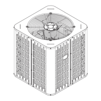
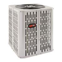
This document is an installer's guide for Heat Pumps, specifically models in the A4HP4001-1E-EN series, including both D and A variants (e.g., A4HP4018D1000A, A4HP4017A1000B). It provides comprehensive instructions for the safe and proper installation, start-up, and troubleshooting of these outdoor heat pump units.

Function Description:

The devices are outdoor heat pump units designed for residential heating, ventilating, and air-conditioning (HVAC) applications. They work in conjunction with indoor units (air handlers or furnaces) to create comfortable, energy-efficient indoor environments. The guide emphasizes the importance of installing approved matched indoor and outdoor systems for maximum efficiency, optimum performance, and best overall system reliability.

Important Technical Specifications:

  • Refrigerant: The units utilize R-410A refrigerant, which operates at 50 to 70% higher pressures than R-22. This necessitates the use of R-410A approved service equipment and POE oil.
  • Refrigerant Line Limits: The maximum total length of refrigerant lines from the outdoor to indoor unit should not exceed 150 feet (including lift). The maximum vertical change (lift) should not exceed 50 feet. Specific service valve connection diameters are provided in Table 5.1, varying by model (e.g., 3/4" or 7/8" for vapor line, 3/8" for liquid line).
  • Factory Charge: Outdoor condensing units are factory charged with the system charge required for the outdoor unit, ten feet of tested connecting line, and the smallest rated indoor evaporative coil match.
  • Defrost Control: Defrost controls have a selectable termination temperature. As shipped, defrost terminates at 47°F, but can be set to 70°F by cutting Jumper J2.
  • Low Voltage Wiring: Maximum wire lengths for low voltage wiring (24 VOLTS) are specified: 18 AWG for 150 Ft., 16 AWG for 225 Ft., and 14 AWG for 300 Ft.
  • Dimensions and Weight: Unit dimensions (H x D x W) and estimated uncrated weights vary by model. For example, A4HP4018D is 32.6 x 29.8 x 29.8 inches and 162 lbs, while A4HP4060D is 44.6 x 34.3 x 34.3 inches and 250 lbs.

Usage Features:

  • Installation Location: Considerations include ensuring unrestricted top discharge area (minimum 5 feet clearance), 3 feet clearance in front of control box and any service side, and positioning at least 12 inches from walls or shrubbery for adequate airflow. Locations near bedrooms or windows where defrost vapor might annoy customers should be avoided.
  • Cold Climate Considerations: For areas with snow accumulation and prolonged freezing temperatures, units should be elevated 3-12 inches above the pad or rooftop to allow for drainage of melted snow and ice. Snow drift barriers are recommended if snow drifts are likely.
  • Refrigerant Line Routing: Precautions are detailed to prevent noise from vibration transmission, including using isolation type hangers when fastening lines to structural elements and insulating lines passing through walls or sills. Minimizing 90-degree turns is also advised.
  • System Start-Up: A step-by-step process is outlined, including setting the thermostat to OFF, applying power, waiting one hour if a compressor crankcase heater accessory is used and ambient temperature is below 70°F, and then setting the thermostat to ON.
  • System Charge Adjustment: Two primary methods are described:
    • Subcooling Charging (Cooling Mode, Above 55°F Outdoor Temp.): This is the recommended method for charging above 55°F ambient. It involves determining the required line length and lift, calculating a final subcooling value using provided charts, and adjusting refrigerant level to match the target liquid gage pressure based on liquid line temperature. The system must stabilize for at least 20 minutes before accurate measurements.
    • Weigh-In Method (Heating Mode, Below 55°F Outdoor Temp.): This method is recommended for charging below 55°F ambient or when power is unavailable. It involves calculating the additional refrigerant needed based on line length beyond 10 feet (0.6 oz/ft multiplier) and weighing in that amount before opening service valves.
    • Fixed Orifice Superheat Charging: A table is provided for charging systems with fixed orifice metering devices, using indoor wet bulb and outdoor dry bulb temperatures to determine target superheat.

Maintenance Features:

  • Safety Warnings: Emphasizes that only qualified personnel should install and service the equipment due to potential hazards. Strict adherence to electrical safety precautions is required when working with live components.
  • Refrigerant Handling: Due to R-410A's hygroscopic POE oil, the system should remain sealed whenever possible. If open to atmosphere for more than 4 hours, compressor oil must be replaced. Never break a vacuum with air, and always change driers when replacing components.
  • Brazing: Instructions include removing pressure tap caps and valve cores, purging with dry nitrogen, wrapping a wet rag around the valve body to avoid heat damage, and installing a drier in the liquid line. Precautions to prevent heat damage to the basepan are noted.
  • Leak Check: After brazing, the refrigerant lines and evaporator coil must be pressurized to 150 PSIG with dry nitrogen, and all brazed locations checked for leaks using a soapy solution.
  • Evacuation: The system must be evacuated until the micron gauge reads no higher than 350 microns, and the vacuum must hold below 500 microns for at least one minute.
  • Service Valves: Detailed steps for opening both gas and liquid service valves are provided, including removing caps, turning stems, and replacing caps, ensuring proper tightening. Extreme caution is advised when opening the Liquid Line Service Valve to avoid abrupt release of system charge.
  • Troubleshooting: A comprehensive "System Faults" table is included, categorizing faults by refrigerant circuit, electrical, and defrost issues, and listing primary and secondary causes.
  • Checkout Procedure: A checklist ensures all installation steps are completed, including leak checks, insulation, securing lines, sealing passages, verifying electrical connections, observing fan operation, checking drain lines, ensuring unobstructed registers, installing air filters, setting correct airflow, and operating the system in all modes for safe operation. A final unit inspection for shifted factory tubing and tight wiring connections is also required.

Trane A4HP4060A1000B Specifications

General IconGeneral
Model NumberA4HP4060A1000B
CategoryHeat Pump
Cooling Capacity (BTU/h)60000
Heating Capacity (BTU/h)60000
HSPF Rating8.2
Voltage208/230
Phase1
Refrigerant TypeR-410A
Compressor TypeScroll

Related product manuals