Do you have a question about the Trane A4HP4017A1000A and is the answer not in the manual?
This document provides comprehensive instructions for the installation, operation, and maintenance of Trane heat pumps, specifically models A4HP4017A1000A through A4HP4060A1000A. The guide emphasizes compliance with national, state, and local codes throughout all installation phases. It is intended for use by qualified personnel with adequate electrical and mechanical experience, as improper installation or servicing can lead to serious injury or property damage.
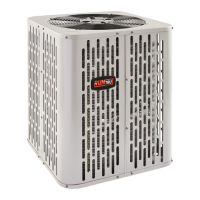
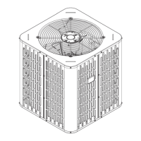
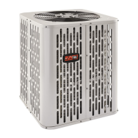
The Trane heat pump is an outdoor condensing unit designed to provide heating and cooling for residential and commercial applications. It operates as part of a split system, working in conjunction with an indoor evaporative coil and air handler. The unit utilizes R-410A refrigerant, which operates at higher pressures than R-22, necessitating the use of R-410A approved service equipment. The system is designed for maximum efficiency, optimum performance, and overall reliability when installed as an approved matched indoor and outdoor system. The heat pump's primary function is to transfer heat, either from the indoor space to the outdoors for cooling, or from the outdoors to the indoor space for heating.
The heat pump is designed for outdoor installation, with considerations for optimal placement to ensure performance and minimize noise. The unit dimensions and weights vary by model, and the guide provides a table for reference. When mounting on a roof, it's crucial to ensure the structure can support the unit's weight. Proper isolation is recommended to prevent sound or vibration transmission to the building. For best performance, the top discharge area should have at least five feet of unrestricted clearance, and three feet of clearance should be maintained in front of the control box and any other side requiring service. Locations near bedrooms or windows where defrost vapor could be annoying should be avoided. A minimum of 12 inches of clearance from walls and surrounding shrubbery is recommended for adequate airflow. In cold climates, the unit should be elevated 3-12 inches above the pad or rooftop to allow for proper drainage of snow and ice during defrost cycles, preventing refreezing and obstruction of drain holes. Snow drift barriers are also suggested in areas prone to heavy snow accumulation. The refrigerant piping limits specify a maximum total line length of 150 feet (including lift) and a maximum vertical change of 50 feet between the outdoor and indoor units. Specific service valve connection diameters are provided for each model. The outdoor condensing units are factory charged with enough refrigerant for the unit itself, ten feet of connecting line, and the smallest rated indoor evaporative coil match. Proper system charge verification via subcooling (for TXV/EEV systems) or superheat (for fixed orifice systems) is essential and should be confirmed against the unit nameplate. Low voltage wiring diagrams are provided for both heat pump and AC systems, including configurations for furnaces and variable speed furnaces. The maximum wire length for low voltage wiring is specified based on wire gauge.
The manual outlines several critical steps for installation and start-up that directly impact maintenance and longevity. Refrigerant line brazing is a key step, requiring the removal of pressure tap caps and valve cores, purging lines with dry nitrogen, and wrapping wet rags around valve bodies to prevent heat damage during brazing. A drier must be installed in the liquid line. Precautions are emphasized to avoid heat damage to the basepan during brazing. After brazing, a leak check is performed by pressurizing the lines and evaporator coil to 150 PSIG with dry nitrogen and checking for leaks with a soapy solution. Any leaks must be repaired before proceeding. Evacuation of the refrigerant lines and indoor coil is crucial, requiring evacuation until the micron gauge reads no higher than 350 microns, followed by a stability check to ensure the gauge does not rise above 500 microns in one minute. Service valves must be opened correctly, with the gas service valve turned 1/4 turn counterclockwise to the fully open position, and the liquid line service valve turned counterclockwise until the stem just touches the rolled edge. Valve stem caps must be replaced and tightened to prevent leaks. Electrical connections, both high and low voltage, must comply with all codes. A separate disconnect switch should be installed at the outdoor unit, and flexible electrical conduit is recommended for high voltage connections to minimize vibration noise. The outdoor unit must be properly grounded. System start-up involves setting the thermostat to OFF, applying power, waiting one hour if a compressor crankcase heater is used and the ambient temperature is below 70°F, and then setting the thermostat to ON. System charge adjustment is a critical maintenance step. For systems with TXV or EEV indoor metering devices, subcooling charging is recommended above 55°F outdoor ambient temperature. The guide provides charts to determine the final subcooling value based on total line length and lift. For outdoor temperatures below 55°F, the weigh-in method in heating mode is recommended. The system must be stabilized by operating for a minimum of 20 minutes before accurate measurements are made. A comprehensive checkout procedure is provided, including verifying refrigerant lines are leak-free and properly insulated, securing and isolating all lines, sealing passages, checking electrical connections, observing outdoor fan operation, ensuring the indoor coil drain line drains freely, confirming supply registers and return grilles are open, verifying a return air filter is installed, and ensuring correct airflow settings. The entire system should be operated in each mode to ensure safe operation. A troubleshooting guide is included to diagnose common system faults related to the refrigerant circuit, electrical components, and defrost function, categorizing potential causes as primary or secondary.