EasyManua.ls Logo

Trane A4HP4036A1000B User Manual

Trane A4HP4036A1000B
28 pages
To Next Page IconTo Next Page
Page #1 background imageLoading...
Page #1 background image
Installers Guide
May 2022
88-A4HP4001-1E-EN
SAFETY WARNING
Only qualified personnel should install and service the equipment. The installation, starting up, and servicing of heating, ventilating,
and air-conditioning equipment can be hazardous and requires specific knowledge and training. Improperly installed, adjusted or
altered equipment by an unqualified person could result in death or serious injury. When working on the equipment, observe all pre-
cautions in the literature and on the tags, stickers, and labels that are attached to the equipment.
Models
A4HP4018D1000A A4HP4017A1000B
A4HP4024D1000A A4HP4018A1000B
A4HP4030D1000A A4HP4023A1000B
A4HP4036D1000A A4HP4024A1000B
A4HP4042D1000A A4HP4030A1000B
A4HP4048D1000A A4HP4036A1000B
A4HP4060D1000A A4HP4042A1000B
A4HP4048A1000B
A4HP4060A1000B
Note: “Graphics in this document are for representation only.
Actual model may differ in appearance.”
Heat Pumps
Question and Answer IconNeed help?

Do you have a question about the Trane A4HP4036A1000B and is the answer not in the manual?

Trane A4HP4036A1000B Specifications

General IconGeneral
ModelA4HP4036A1000B
TypeHeat Pump
Cooling Capacity36000 BTU/H
Heating Capacity36000 BTU/H
SEER Rating16
RefrigerantR-410A
Voltage208/230V
Phase1
Compressor TypeScroll
Sound Level (Outdoor Unit)76 dB

Summary

Section 1. Safety

Safety Information for Experienced Individuals

General safety information for individuals with HVAC experience.

R-410A Refrigerant Handling Precautions

Guidelines for safely handling R-410A refrigerant and POE oil.

Liquid Line Service Valve Caution

Warning regarding the careful operation of the liquid line service valve.

Electrical Safety Warning

Critical safety precautions for working with live electrical components.

R-410A Refrigerant Unit Warning

Warning about R-410A refrigerant pressures and required tools.

Section 2. Unit Location Considerations

Service Valves Locations

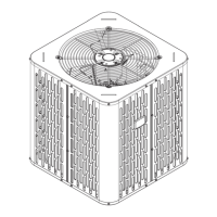
Identifies the locations of key service valves on the unit.

Section 5. Refrigerant Line Considerations

Section 7. Refrigerant Line Brazing

Section 8. Refrigerant Line Leak Check

Section 9. Evacuation

Section 10. Service Valves

Section 11. Electrical - Low Voltage

Section 12. Electrical - High Voltage

Section 13. Start Up

Section 14. System Charge Adjustment

Temperature Measurements

Guidance on measuring temperatures for system charging.

Subcooling Charging in Cooling (Above 55° F Outdoor Temp.)

Method for subcooling charge adjustment when outdoor temp is above 55°F.

Subcooling Charging Below 55° F Outdoor Temp. (In Heating Only)

Method for charging in heating mode when outdoor temp is below 55°F.

Section 15. Checkout Procedures and Troubleshooting

Operational And Checkout Procedures

Checklist for final operational and checkout procedures after installation.

Troubleshooting

Table outlining system faults and their primary/secondary causes.

Related product manuals