Do you have a question about the Trane A4HP4036D and is the answer not in the manual?
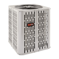
This document serves as an installer's guide for heat pumps, specifically covering models A4HP4017D, A4HP4018D, A4HP4024D, A4HP4030D, A4HP4036D, A4HP4042D, A4HP4048D, and A4HP4060D. It provides comprehensive instructions for the safe and efficient installation, startup, and maintenance of these units. The guide emphasizes that only qualified personnel with adequate electrical and mechanical experience should perform installation and servicing to prevent personal injury or property damage. All installation phases must comply with national, state, and local codes.
The guide begins with crucial safety warnings, highlighting the importance of using R-410A approved service equipment due to the higher operating pressures of this refrigerant compared to R-22. It also warns about the hygroscopic nature of POE oil used in R-410A systems, stressing the need to keep the system sealed and to replace compressor oil if the system has been open to the atmosphere for more than four hours. Users are cautioned against venting refrigerant gases into the atmosphere and are advised to change driers when opening the system for component replacement. Extreme caution is advised when opening the Liquid Line Service Valve to prevent abrupt release of system charge. The document also includes a warning about live electrical components, emphasizing the need to follow all electrical safety precautions during installation, testing, servicing, and troubleshooting. A specific caution is given regarding scroll compressor dome temperatures, which can be hot and cause burns. Furthermore, a general warning about chemicals, including lead, known to the State of California to cause cancer and birth defects, is included, directing users to www.P65Warnings.ca.gov for more information.
The installation process starts with unit location considerations. The guide provides unit dimensions and weight, noting that weight values are estimated uncrated. It advises ensuring the roof can support the unit's weight if mounted on a roof and recommends proper isolation to alleviate sound or vibration transmission. Suggested locations for best reliability include ensuring the top discharge area is unrestricted for at least five feet above the unit and providing three feet of clearance in front of the control box and any other side requiring service. It is not recommended to install the unit where noise may disturb building occupants, such as near sleeping quarters or windows of living areas. The outdoor unit should be positioned a minimum of 12 inches from any wall or surrounding shrubbery to ensure adequate airflow. Locations near windows where condensation and freezing defrost vapor could annoy a customer should be avoided, and the unit should be far enough from any structure to prevent excess roof runoff water or icicles from falling directly on it. For cold climates, the guide recommends elevating units 3-12 inches above the pad or rooftop to allow for drainage of melted snow and ice and to prevent drain holes from being obstructed. Avoiding locations prone to snow drifts or installing a snow drift barrier is also suggested.
Unit preparation involves checking for damage upon arrival and reporting any promptly to the carrier. For setting the unit, the guide specifies that the support pad, such as a concrete slab, should be at least one inch larger than the unit on all sides, separate from any structure, level, and high enough above grade for drainage. Pad location must comply with all relevant codes.
Refrigerant line considerations are detailed, including maximum total line length (150 feet, including lift) and maximum vertical change (50 feet). Service valve connection diameters are provided in a table. The outdoor condensing units are factory charged with the system charge required for the unit, ten feet of tested connecting line, and the smallest rated indoor evaporative coil match. The guide stresses verifying proper system charge via subcooling (TXV/EEV) or superheat (fixed orifice) per the unit nameplate. The vapor line must always be insulated, and direct metal-to-metal contact between the liquid and vapor lines should be avoided. For existing refrigerant lines, it's crucial to ensure all joints are brazed, not soldered, and that the lines are the correct size, free of leaks, acid, and oil.
Refrigerant line routing precautions include preventing noise within the building structure due to vibration transmission. Isolation-type hangers should be used when fastening lines to floor joists or framing, and lines running through walls or sills should be insulated and isolated. Lines should be isolated from all ductwork, and the number of 90-degree turns should be minimized.
Refrigerant line brazing instructions involve removing caps or plugs, deburring pipe ends, and cleaning tubing surfaces. Pressure tap caps and valve cores must be removed from both service valves before purging refrigerant lines and the indoor coil with dry nitrogen. A wet rag should be wrapped around the valve body to prevent heat damage during brazing, and the dry nitrogen purge should continue until all brazing is completed. A drier must be installed in the liquid line. Precautions are advised to avoid heat damage to the basepan. After brazing, valve cores should be replaced once service valves have cooled.
A leak check is performed by pressurizing refrigerant lines and the evaporator coil to 150 PSIG with dry nitrogen and checking for leaks with a soapy solution. Any leaks must be repaired before proceeding.
Evacuation of refrigerant lines and the indoor coil is critical. The system must be evacuated until the micron gauge reads no higher than 350 microns. Evacuation is complete if the micron gauge does not rise above 500 microns in one minute after closing the valve to the vacuum pump.
Opening the service valves is the next step. The gas service valve is opened by turning the valve stem 1/4 turn counterclockwise to the fully open position, then replacing the cap. For the liquid service valve, the stem is turned counterclockwise until it just touches the rolled edge (approximately five turns), then the cap is replaced. Leak check and evacuation must be completed before opening service valves.
Electrical connections are covered, including low voltage and high voltage wiring. The maximum wire length for low voltage wiring is specified based on wire size (e.g., 18 AWG for 150 ft, 14 AWG for 300 ft). Low voltage hook-up diagrams are provided for heat pump systems, AC systems, and systems with variable speed furnaces. Defrost control settings are explained, including how to adjust the termination temperature and initiate a forced defrost for troubleshooting. High voltage power supply must match the equipment nameplate and comply with all codes. A separate disconnect switch must be installed at the outdoor unit, and flexible electrical conduit is recommended for high voltage connections to prevent noise. The outdoor unit must be grounded per national, state, and local code requirements.
System startup involves ensuring all previous sections are completed, setting the system thermostat to OFF, and turning on disconnects to apply power. A one-hour wait is required before starting the unit if a compressor crankcase heater accessory is used and the outdoor ambient is below 70°F. Finally, the system thermostat is set to ON.
System charge adjustment is detailed for systems with TXV, EEV, or piston metering devices. For outdoor temperatures above 55°F, subcooling in cooling mode is the recommended charging method. Charts are provided to determine the final subcooling value based on total line length and vertical change. The system must operate for a minimum of 20 minutes to stabilize before accurate measurements can be made. For outdoor temperatures below 55°F, the weigh-in method in heating mode is recommended. This involves calculating the additional refrigerant needed based on line length beyond 10 feet.
Checkout procedures and troubleshooting are the final steps. A comprehensive checklist ensures proper installation and operation, including leak checks, insulation, securing lines, sealing passages, verifying electrical connections, observing fan operation, ensuring free drain line drainage, unobstructed registers, installed air filter, correct airflow setting, and operating the system in all modes. A system faults table is included for troubleshooting, categorizing faults by refrigerant circuit, electrical issues, and defrost problems, and identifying primary and secondary causes.
| Type | Heat Pump |
|---|---|
| HSPF Rating | Up to 8.2 |
| Refrigerant | R-410A |
| Voltage | 208/230V |
| Phase | 1 |
| Compressor Type | Scroll |
| Cooling Capacity | 36000 BTU/h |
| Heating Capacity | 36000 BTU/h |