EasyManua.ls Logo

Trane A4HP4018D1000A User Manual

Trane A4HP4018D1000A
28 pages
To Next Page IconTo Next Page
Page #1 background imageLoading...
Page #1 background image
Installers Guide
May 2022
88-A4HP4001-1E-EN
SAFETY WARNING
Only qualified personnel should install and service the equipment. The installation, starting up, and servicing of heating, ventilating,
and air-conditioning equipment can be hazardous and requires specific knowledge and training. Improperly installed, adjusted or
altered equipment by an unqualified person could result in death or serious injury. When working on the equipment, observe all pre-
cautions in the literature and on the tags, stickers, and labels that are attached to the equipment.
Models
A4HP4018D1000A A4HP4017A1000B
A4HP4024D1000A A4HP4018A1000B
A4HP4030D1000A A4HP4023A1000B
A4HP4036D1000A A4HP4024A1000B
A4HP4042D1000A A4HP4030A1000B
A4HP4048D1000A A4HP4036A1000B
A4HP4060D1000A A4HP4042A1000B
A4HP4048A1000B
A4HP4060A1000B
Note: “Graphics in this document are for representation only.
Actual model may differ in appearance.”
Heat Pumps
Question and Answer IconNeed help?

Do you have a question about the Trane A4HP4018D1000A and is the answer not in the manual?

Trane A4HP4018D1000A Specifications

General IconGeneral
BrandTrane
ModelA4HP4018D1000A
CategoryHeat Pump
LanguageEnglish

Summary

Unit Location Considerations

Unit Dimensions and Weight

Details the physical dimensions and weight of various heat pump models.

Service Valves Locations

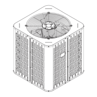
Identifies the location of key service valves on the outdoor unit.

Refrigerant Piping Limits

Specifies maximum total and vertical lengths for refrigerant lines.

Suggested Locations for Best Reliability

Provides recommendations for optimal outdoor unit placement for reliability.

Cold Climate Considerations

Offers precautions for installing units in cold weather with snow/ice.

Unit Preparation

Prepare The Unit For Installation

Instructions for checking and preparing the unit before installation.

Setting the Unit

Pad Installation

Guidelines for installing the unit on a support pad.

Refrigerant Line Considerations

Refrigerant Line and Service Valve Connection Sizes

Details line sizes and service valve connection sizes for different models.

Factory Charge

Explains factory charge details and verification methods.

Required Refrigerant Line Length

Prompts for recording line length and vertical change for later use.

Refrigerant Line Insulation

Emphasizes insulation requirements for the vapor line.

Reuse Existing Refrigerant Lines

Precautions for using existing refrigerant lines during retrofit.

Refrigerant Line Routing

Precautions

Guidelines to prevent noise from vibration transmission via refrigerant lines.

Refrigerant Line Brazing

Braze The Refrigerant Lines

Step-by-step instructions for brazing refrigerant lines.

Refrigerant Line Leak Check

Check For Leaks

Procedure for pressurizing lines and checking for leaks.

Evacuation

Evacuate the Refrigerant Lines and Indoor Coil

Steps for evacuating refrigerant lines and indoor coil using a micron gauge.

Service Valves

Open the Gas Service Valve

Instructions for opening the gas service valve.

Service Valves (Continued)

Open the Liquid Service Valve

Procedure for opening the liquid service valve, with a warning.

Electrical - Low Voltage

Low Voltage Maximum Wire Length

Table showing maximum wire lengths for low voltage wiring based on gauge.

Low Voltage Hook-up Diagrams

Diagrams illustrating low voltage wiring for heat pump and AC systems.

Defrost Control

Details on defrost control settings and checkout procedures.

Electrical - High Voltage

High Voltage Power Supply

Information on high voltage power supply requirements and safety.

High Voltage Disconnect Switch

Guidance on installing a separate disconnect switch for high voltage.

High Voltage Ground

Requirements for grounding the outdoor unit.

Start Up

System Start Up

Step-by-step guide for starting up the installed system.

System Charge Adjustment

Temperature Measurements

Instructions for taking necessary temperature measurements for charging.

Subcooling Charging in Cooling (Above 55° F Outdoor Temp.)

Method for subcooling charge adjustment when outdoor temp is above 55°F.

Subcooling Charging Below 55° F Outdoor Temp. (In Heating Only)

Method for charging in heating mode when outdoor temp is below 55°F.

Calculating Charge Using the Weigh-In Method

Steps to calculate refrigerant charge using the weigh-in method.

Checkout Procedures and Troubleshooting

Operational And Checkout Procedures

Lists procedures for final operational checks and system checkout.

Troubleshooting

Table of system faults, their causes, and troubleshooting steps.

Related product manuals