10 88-A4HP4001-1F-EN
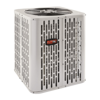
Isolation In Wall Spaces
Side View
Wall
Isolator
Line Set
8 Feet Maximum
Secure Vapor Line using isolators every 8 ft. Secure Liquid Line
directly to Vapor Line using tape, wire, or other appropriate
method every 8 ft.
8 Feet Maximum
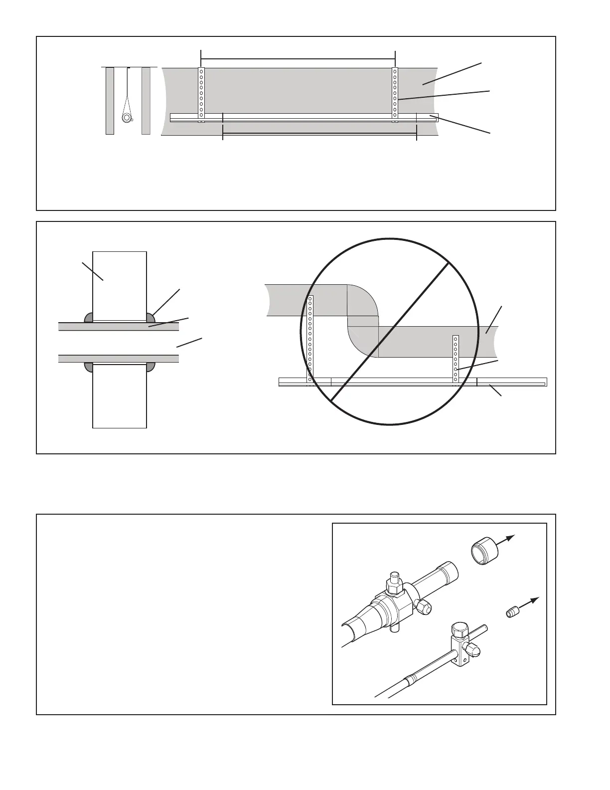
Isolation Through Wall
DO NOT hang line sets from ductwork
Sealant
Insulation
Vapor Line
Wall
Ductwork
Isolator
Line Set
Section 7. Refrigerant Line Brazing
7.1 Braze The Refrigerant Lines
STEP 1 - Remove caps or plugs. Use a debur-
ing tool to debur the pipe ends. Clean both
internal and external surfaces of the tubing
using an emery cloth.