EasyManua.ls Logo

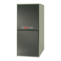
Trane AUD2B060A9V3VB User Manual

Trane AUD2B060A9V3VB
24 pages
To Next Page IconTo Next Page
Page #1 background imageLoading...
Page #1 background image
Variable Speed, 2-Stage
Upflow / Horizontal and
Downflow / Horizontal, Gas-Fired Furnaces,
“Fan Assisted Combustion System”
A341789P10
Installer’s Guide
Downflow / Horizontal*
Upflow / Horizontal*
For VENT SIZING INFORMATION see:
USA
National Fuel Gas Code ........... ANSI Z223.1/NFPA 54 (latest version)
CANADA
Natural Gas Installation Code ........CAN/CGA-B149.1 (latest version)
Propane Installation Code ...............CAN/CGA-B149.2 (latest version)
USA/CANADA ALTERNATE —
Category I Venting Guide ...........Pub. No. 18-CH23D1 (latest version)
*Horizontal Conversion for these furnaces may be left or right side rotation.
ALL phases of this installation must comply with NATIONAL, STATE AND LOCAL CODES
IMPORTANT This Document is customer property and is to remain with this unit.
Please return to service information pack upon completion of work.
*__First letter may be “A” or “T”
*UD2B060A9V3VB
*UD2B080A9V3VB
*UD2C080A9V4VB
*UD2C080B9V4VB
*UD2B100A9V3VB
*UD2C100A9V5VB
*UD2C100B9V5VB
*UD2D120A9V5VB
*UD2D120B9V5VB
*UD2D140A9V5VB
*DD2B060A9V3VA
*DD2B080A9V3VA
*DD2C100A9V5VA
*DD2D120A9V5VA
*DD2-9V
*UD2-9V
1 8 - CD3 1 D1 - 3
Question and Answer IconNeed help?

Do you have a question about the Trane AUD2B060A9V3VB and is the answer not in the manual?

Trane AUD2B060A9V3VB Specifications

General IconGeneral
BrandTrane
ModelAUD2B060A9V3VB
CategoryFurnace
TypeGas
Heating Capacity60, 000 BTU
Input BTU60, 000 BTU
Output BTU57, 000 BTU
Efficiency Rating95%
AFUE95%
StagesTwo-stage
Blower Motor TypeECM
Fuel TypeNatural Gas
VentilationDirect vent
IgnitionHot Surface Ignition
Warranty10 years
Blower MotorVariable-speed

Summary

Safety Section

Carbon Monoxide Poisoning Hazard

Details the critical steps to prevent carbon monoxide poisoning when placing appliances into operation.

Fire or Explosion Hazard

Highlights the severe risks of fire or explosion due to improper handling or maintenance of the furnace.

General Installation Instructions

Location and Clearances

Provides essential guidelines for selecting the furnace location and maintaining required clearances.

Air for Combustion and Ventilation

General Venting Instructions

Vent Piping

Covers general requirements and standards for furnace vent piping installation.

Electrical Connections

Field Wiring Diagrams

Gas Piping

Combustion and Input Check

Procedure for checking combustion and verifying furnace input rate.

Gas Valve Adjustment

2nd Stage (HI) Manifold Pressure Adjustment

Instructions for adjusting the manifold pressure for the 2nd stage of gas heat.

1st Stage (LO) Manifold Pressure Adjustment

Instructions for adjusting the manifold pressure for the 1st stage of gas heat.

Start Up and Adjustment

Control and Safety Switch Adjustment

Limit Switch Check Out

Procedure for verifying the proper operation of the furnace limit switch.

Abnormal Conditions

Excessive Combustion Pressure (Wind in Excess of 40 M.P.H.) Vent or Flue Blockage

Addresses issues caused by excessive combustion pressure or blocked vents.

Loss of Flame

Describes the system response and actions taken if flame is lost during operation.

Gas Supply Failure

Details the system's reaction to a loss of gas supply during operation.

Induced Draft Blower Failure

Explains the consequences of a failure in the induced draft blower system.

What to Do If You Smell Gas

Crucial steps to take immediately if a gas leak is detected.

Related product manuals