Service Facts
© 2011 Trane All Rights Reserved
NOTICE: Since the manufacturer has a policy of continuous product and product data
improvement, it reserves the right to change design and specifications with-
out notice.
PRODUCT SPECIFICATIONS
1
MODEL
TYPE
RATINGS 2
40% (low) heat Input BTUH
40% (low) heat Capacity BTUH (ICS) 36
100% (high) heat Input BTUH
100% (high) heat Capacity BTUH (ICS) 3
Temp. rise (Min.-Max.) °F.
AFUE
BLOWER DRIVE
Diameter - Width (In.)
No. Used
Speeds (No.)
CFM vs. in. w.g.
Motor HP
R.P.M.
Volts / Ph / Hz
COMBUSTION FAN - Type
Drive - No. Speeds
Motor HP - RPM
Volts / Ph / Hz
FLA
FILTER — Furnished?
Type Recommended
Hi Vel. (No.-Size-Thk.)
VENT — Size (in.)
HEAT EXCHANGER
Type -Fired
-Unfired
Gauge (Fired)
ORIFICES — Main
Nat. Gas. Qty. — Drill Size
L.P. Gas Qty. — Drill Size 5
GAS VALVE
PILOT SAFETY DEVICE
Type
BURNERS — Type
Number
POWER CONN. — V / Ph / Hz 4
Ampacity (In Amps)
Max. Overcurrent Protection (Amps)
PIPE CONN. SIZE (IN.)
DIMENSIONS
Crated (In.)
WEIGHT
Shipping (Lbs.) / Net (Lbs)
*UHMB080ACV3VA
Upflow/ Horizontal
32,000
30,000
80,000
75,000
35 - 65
95.0
DIRECT
10 x 8
1
Variable
See Fan Performance Table
1/2
Variable
115/1/60
Centrifugal
Direct - Variable
1/50 - 5000
33 - 110/3/60 - 180
5.8
Yes
High Velocity
1 - 17x25 - 1 in.
2 Round
Aluminized Steel - Type I
20
4 — 45
4 — 56
Modulating
Hot Surface Igniter
Multiport Inshot
4
115/1/60
8.7
15
1/2
H x W x D
41-3/4 x 19-1/2 x 30-1/2
168 / 156
IMPORTANT — This document contains a wiring diagram and service information. This is customer property and is to
remain with this unit. Please return to service information pack upon completion of work.
DISCONNECT POWER BEFORE SERVICING
WARNING
*UHMB060ACV3VA
Upflow/ Horizontal
24,000
23,000
60,000
57,000
35 - 65
95.0
DIRECT
10 x 8
1
Variable
See Fan Performance Table
1/2
Variable
115/1/60
Centrifugal
Direct - Variable
1/50 - 5000
33 - 110/3/60 - 180
5.8
Yes
High Velocity
1 - 17x25 - 1 in.
2 Round
Aluminized Steel - Type I
20
3 — 45
3 — 56
Modulating
Hot Surface Igniter
Multiport Inshot
3
115/1/60
8.7
15
1/2
H x W x D
41-3/4 x 19-1/2 x 30-1/2
158 / 146
*UHMC100ACV4VA
Upflow/ Horizontal
40,000
38,000
100,000
95,000
35 - 65
95.0
DIRECT
10 x 10
1
Variable
See Fan Performance Table
1
Variable
115/1/60
Centrifugal
Direct - Variable
1/50 - 5000
33 - 110/3/60 - 180
7.8
Yes
High Velocity
1 - 20x25 - 1 in.
3 Round
Aluminized Steel - Type I
20
5 — 45
5 — 56
Modulating
Hot Surface Igniter
Multiport Inshot
5
115/1/60
11.2
20
1/2
H x W x D
41-3/4 x 23 x 30-1/2
197 / 185
*UHMD120ACV5VA
Upflow/ Horizontal
54,000
52,000
120,000
114,000
40 - 70
95.0
DIRECT
10 x 10
1
Variable
See Fan Performance Table
1
Variable
115/1/60
Centrifugal
Direct - Variable
1/50 - 5000
33 - 110/3/60 - 180
10.2
Yes
High Velocity
1 - 24x25 - 1 in.
3 Round
Aluminized Steel - Type I
20
6 — 45
6 — 56
Modulating
Hot Surface Igniter
Multiport Inshot
6
115/1/60
14.2
20
1/2
H x W x D
41-3/4 x 26-1/2 x 30-1/2
206 / 193
1 Central Furnace heating designs are certified to ANSI Z21.47 / CSA 2.3.
2 For U.S. applications, above input ratings (BTUH) are up to 2,000 feet, derate 4% per 1,000 feet for elevations above 2,000 feet above sea level.
For Canadian applications, above input ratings (BTUH) are up to 4,500 feet, derate 4% per 1,000 feet for elevations above 4,500 feet above sea level.
3 Based on U.S. government standard tests.
4 The above wiring specifications are in accordance with National Electrical Code; however, installations must comply with local codes.
5 Furnace ships in natural gas configuration. The LP conversion kit used with the modulating furnace is BAYLPSS220B or BAYLPKT220B.
6 45% (low) heat for *UHM1D120ACV5VA.
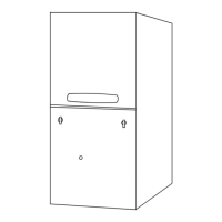
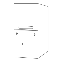
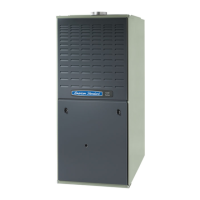
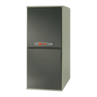
Upflow/ Horizontal Left and Downflow/ Horizontal Right,
Gas-Fired, Direct/Non-Direct Vent, Variable Speed,
Modulating, Condensing, Communicating Furnaces
*UHMB060ACV3VA
*UHMB080ACV3VA
*UHMC100ACV4VA
*UHMD120ACV5VA
*DHMB060BCV3VA
*DHMB080ACV3VA
*DHMC100ACV4VA
*DHMD120BCV5VA
* First letter may be “A” or “T"
This furnace can be configured
for Communicating or 24 VAC
modes.
*UHM-DHM-SF-1H