EasyManua.ls Logo

Trane AUX2B060A9362A User Manual

Trane AUX2B060A9362A
38 pages
To Next Page IconTo Next Page
Page #1 background imageLoading...
Page #1 background image
ALL phases of this installation must comply with NATIONAL, STATE AND LOCAL CODES
IMPORTANT This Document is customer property and is to remain with this unit.
Please return to service information pack upon completion of work.
Installer’s Guide
*__First letter may be “A” or “T”
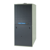
Upflow / Horizontal & Downflow / Horizontal,
Gas-Fired, Direct Vent, 2-Stage Condensing
Furnaces with Variable Speed Inducer
A341624P03
*UX2B060A9362A *UX2B080A9422A *UX2C100A9482A
*UX2D120A9602A *DX2B060A9362A *DX2B080A9422A
*DX2C100A9482A *DX2D120A9602A
UPFLOW / HORIZONTAL LEFT
DOWNFLOW / HORIZONTAL RIGHT
*UX2 *DX2
UPFLOW
DOWNFLOW
1
11
18
88
8-
--
-C
CC
CD
DD
D1
11
19
99
9D
DD
D8
88
8-
--
-1
11
18
88
8
Question and Answer IconNeed help?

Do you have a question about the Trane AUX2B060A9362A and is the answer not in the manual?

Trane AUX2B060A9362A Specifications

General IconGeneral
ModelAUX2B060A9362A
Heating Capacity60, 000 BTU
Efficiency Rating80% AFUE
Fuel TypeNatural Gas
StagesSingle Stage
Ignition TypeHot Surface Ignition
Filter TypeStandard
Warranty5-Year parts limited warranty

Summary

SAFETY SECTION

CARBON MONOXIDE POISONING HAZARD

Steps to follow for each appliance connected to the venting system.

FIRE OR EXPLOSION HAZARD

Failure to follow safety warnings can lead to serious injury or death.

MASSACHUSETTS INSTALLATION REQUIREMENTS

CARBON MONOXIDE DETECTOR INSTALLATION

Requirements for CO detectors, signage, and inspection for side wall venting.

FIELD WIRING DIAGRAMS

2 STAGE HEATING WITH 1 STAGE THERMOSTAT

Wiring diagram for a 2-stage furnace using a 1-stage thermostat.

2 STAGE HEAT / 1 STAGE COOLING WIRING

Wiring diagrams for various thermostat configurations with 2-stage heating.

2 STAGE HEATING WITH 2 STAGE THERMOSTAT

Wiring diagram for a 2-stage furnace using a 2-stage thermostat.

TWINNING CONNECTION DIAGRAMS

1 STAGE HEAT / 1 STAGE COOLING TWINNING

Wiring diagrams for connecting two furnaces with a 1-stage thermostat.

2 STAGE HEAT / 1 STAGE COOLING TWINNING

Wiring diagrams for connecting two furnaces with a 2-stage thermostat.

TWINNING CONNECTION DIAGRAM

2 STAGE HEAT / 2 STAGE COOLING TWINNING

Wiring diagrams for connecting two furnaces with 2-stage heating/cooling.

GAS PIPING INSTALLATION

GAS PIPING AND FITTING REQUIREMENTS

Guidelines for gas piping installation, joint compound, and drip legs.

GASVALVE ADJUSTMENT

MANIFOLD PRESSURE ADJUSTMENT

Steps for adjusting 1st and 2nd stage manifold pressure for gas valve.

START-UP AND ADJUSTMENT

PRELIMINARY INSPECTIONS AND LIGHTING

Initial checks before start-up, gas leak checks, and lighting procedures.

SEQUENCE OF OPERATION

Detailed steps of furnace operation based on thermostat calls.

CONTROL AND SAFETY SWITCHES

LIMIT SWITCH AND AIRFLOW ADJUSTMENT

Procedures for checking limit switches and adjusting airflow.

ABNORMAL CONDITIONS

FURNACE OPERATIONAL ISSUES

Troubleshooting common abnormal conditions like pressure errors, flame loss, and blockages.

FAULT CODE RECOVERY

Related product manuals