8
Installation
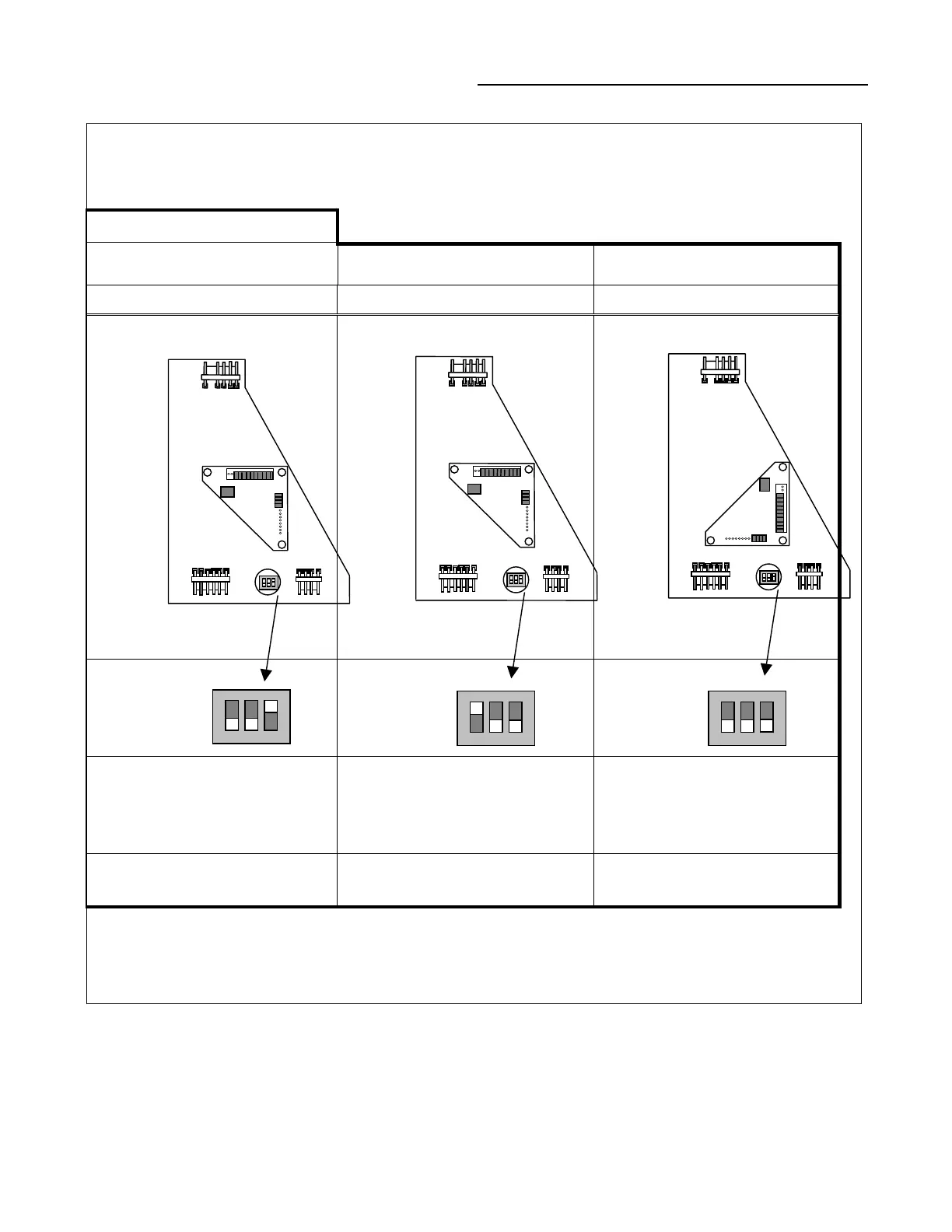
Figure 6
Dip Switch Settings and Daughter-board Configurations.
Default Configuration
1
Fig. 7a Fig. 7b Fig. 7c
IPCB TCI/COMM4
TCI/COMM3
2
IPCB
Non-Isolated Com3 or Com4
Dip Switch – Off, Off, On
TCI
Non-Isolated Com3 or Com4
Dip Switch – On, Off, Off
TCI
Isolated Com3
Dip Switch – Off, Off, Off
Remote Human Interface Tracer Summit Comm4 Tracer Summit, 100, L, etc.
Notes:
1.
The module ships in the IPCB configuration (Fig. 7a).
2.
Please refer to Figure 8 for proper daughter-board rotation procedure.
123
ON
123
ON
123
ON