8
RLC-SVX023B-GB
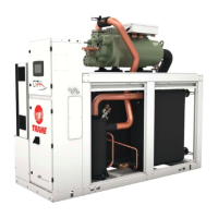
Component location for typical RTSF Unit
2 = Power cable gland plate
for customer wiring
4 = Suction line
5 = Oil separator
6 = Condenser water outlet
7 = Condenser water inlet
8 = Evaporator water outlet
9 = Evaporator water inlet
13 = External control wiring
cable gland plate for
customer wiring
14 = Compressor
15 = Discharge line
16 = Unit nameplate (on the
side of starter/control
panel)
17 = EXV
18 = Condenser
15
14
4
9
8
7
16
13
2
5
17
18
6
5
10
4
11 12
3
1
1 = Control panel
3 = Tracer TD7 interface
4 = Suction line
10 = Auxiliary Oil Cooler (Optional)
11 = Evaporator
12 = Adaptive Frequency Drive
Unit Description
 Loading...