EasyManua.ls Logo

Trane ComfortLink II 4TTV0X61A1000A - User Manual

Trane ComfortLink II 4TTV0X61A1000A
32 pages
To Next Page IconTo Next Page
Loading...
SSAAFFEETTYY WWAARRNNIINNGG
Only qualified personnel should install and service the equipment. The installation, starting up, and servicing of heating, ventilating, and air-conditioning
equipment can be hazardous and requires specific knowledge and training. Improperly installed, adjusted or altered equipment by an unqualified person
could result in death or serious injury. When working on the equipment, observe all precautions in the literature and on the tags, stickers, and labels that
are attached to the equipment.
August 2022
1188--BBCC110055DD11--11DD--EENN
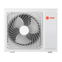
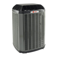
TRANE Link or ComfortLink II
Variable Speed Heat Pumps and Air Conditioners
4TWV0X24A1000A
4TWV0X36A1000A
4TWV0X48A1000A
4TWV0X60A1000A
4TTV0X24A1000A
4TTV0X36A1000A
4TTV0X48A1000A
4TTV0X60A1000A
4TTV0X61A1000A
TM
The Diagnostics Mobile App is available by scanning a QR
code located inside this unit or by searching for the Link
Diagnostics App in your App Store
®
.
NNoottee:: “Graphics in this document are for representation only. Actual
model may differ in appearance.”
NNoottee:: This unit can be used in Comfortlink
II (“clii”) mode or Link
mode.
Installer’s Guide
Question and Answer IconNeed help?

Do you have a question about the Trane ComfortLink II 4TTV0X61A1000A and is the answer not in the manual?

Trane ComfortLink II 4TTV0X61A1000A Specifications

General IconGeneral
BrandTrane
ModelComfortLink II 4TTV0X61A1000A
CategoryAir Conditioner
LanguageEnglish

Summary

Safety Warnings and Precautions

General Safety Warnings

Crucial safety warnings related to voltage, refrigerant, heat, grounding, and connections.

Unit Preparation and Setup

Setting Up the Unit

Procedures for preparing and setting up the outdoor unit, including pad installation.

Refrigerant Line Brazing

Refrigerant Line Leak Check

Refrigerant Line and Indoor Coil Evacuation

Service Valve Operation

High Voltage Electrical Connections

System Start-Up Procedure

System Charge Adjustment

Subcool Charging Correction Charts

Refrigerant Charging Chart

Provides R-410A design subcooling values based on liquid temperature and pressure.

Unit Charging Procedure

Subcooling Charging Below 55°F Outdoor (Heating Only)

Heat Pump Defrost Control

Installation Checkout Procedures

Related product manuals