18-BC105D1-1D-EN
17
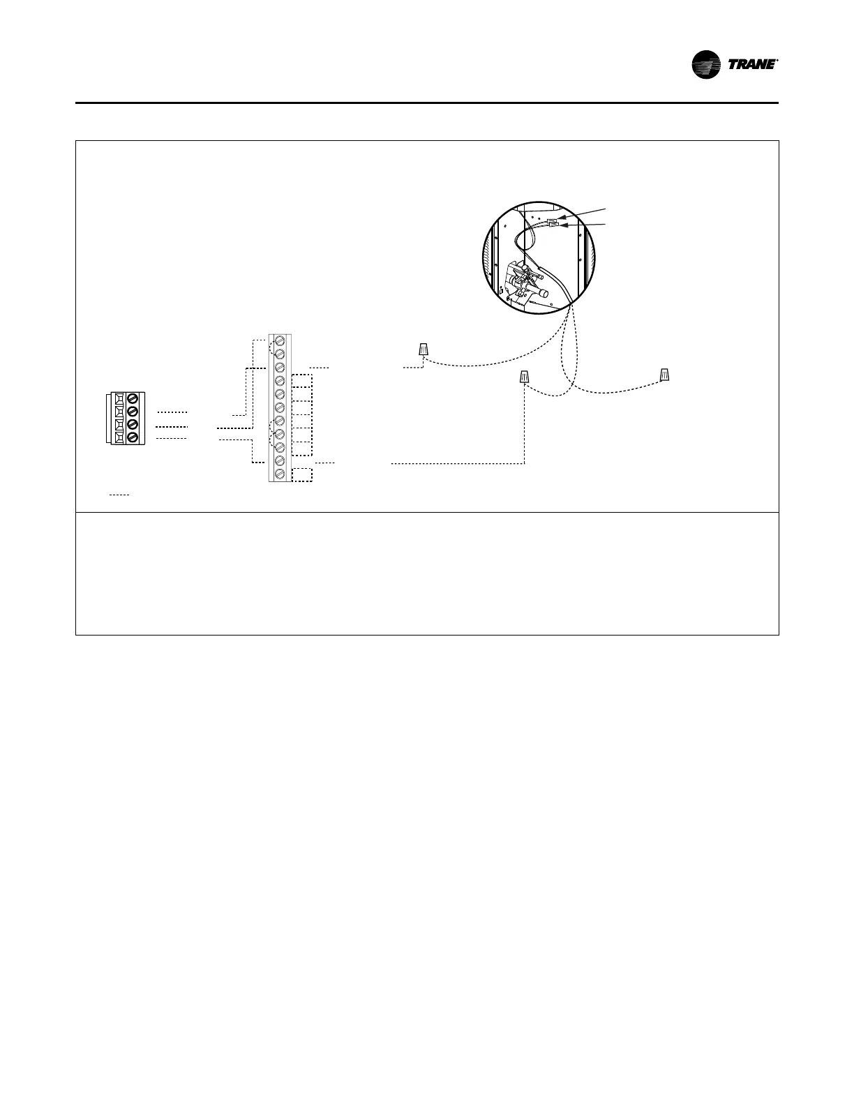
Table 22. Low Voltage Hook-up Diagrams in clii mode
Figure 2. Fully Communicating System
Neatly bundle all low voltage
wires as shown.
(Not used in clii mode)
DH
DL
Communicating
Comfort Control
W1
W2
W3
G
Y2
B
O
BK
D
Y1
R
Field wiring
Brown
Blue
Brown
Blue
Red
B - Blue
D - Note 3
D
R
B
Note 1
&
Note 2
Red
Only used for
Load Shed
(Cap off if
not used)
Communicating
Indoor Unit
Note 4
Note 5
Communicating Outdoor Unit
1. In communicating mode, unused terminals are non-functional. Do not use.
2. Terminals present will vary by indoor model.
3. “D” is the data line. Installer to select a wire color.
4. If a 3rd party condensate overflow switch is installed, it should be wired in series with R to the thermostat or connected to the External
Switch terminals on the AFC. See External Switch wiring section in the air handler Installer’s Guide.
5. Wire present only on Variable Speed Outdoor Units.
Note: Anti-oxidizing grease is supplied in the documentation package for use when making low voltage field wiring connections at the outdoor
unit. Apply grease to field wiring before installing wire caps to protect these connections from corrosion.
EElleeccttrriiccaall –– LLooww VVoollttaaggee CCoommmmuunniiccaattiinngg
 Loading...