6
18-BC105D1-1D-EN
Table 4. Alternate Refrigerant Line and Service Valve Connection Sizes
Model
Alternate Line Sizes
Service Valve
Connection Sizes
Vapor
Line
Liquid Line Vapor Line Connection Liquid Line Connection
4TWV0X24A
3/4"
(a)
5/16" 3/4" 3/8"
4TWV0X36A
5/8"
(a)
5/16" 3/4" 3/8"
4TWV0X48A
3/4"
(a)
3/8" 7/8" 3/8"
4TWV0X60A
3/4"
(a)
3/8" 7/8" 3/8"
7/8"
(a)
3/8" 7/8" 3/8"
Model
Alternate Line Sizes
Service Valve
Connection Sizes
Vapor
Line
Liquid Line Vapor Line Connection Liquid Line Connection
4TTV0X24A
3/4"
(a)
5/16" 3/4" 3/8"
4TTV0X36A
5/8"
(a)
5/16" 3/4" 3/8"
4TTV0X48A
3/4"
(a)
3/8" 7/8" 3/8"
4TTV0X60A
3/4"
(a)
3/8" 7/8" 3/8"
7/8"
(a)
3/8" 7/8" 3/8"
4TTV0X61A
3/4"
(a)
3/8" 7/8" 3/8"
7/8"
(a)
3/8" 7/8" 3/8"
(a)
The max length of refrigerant lines from outdoor to indoor unit MUST NOT exceed 150 feet. The max vertical change MUST NOT exceed 50 feet.
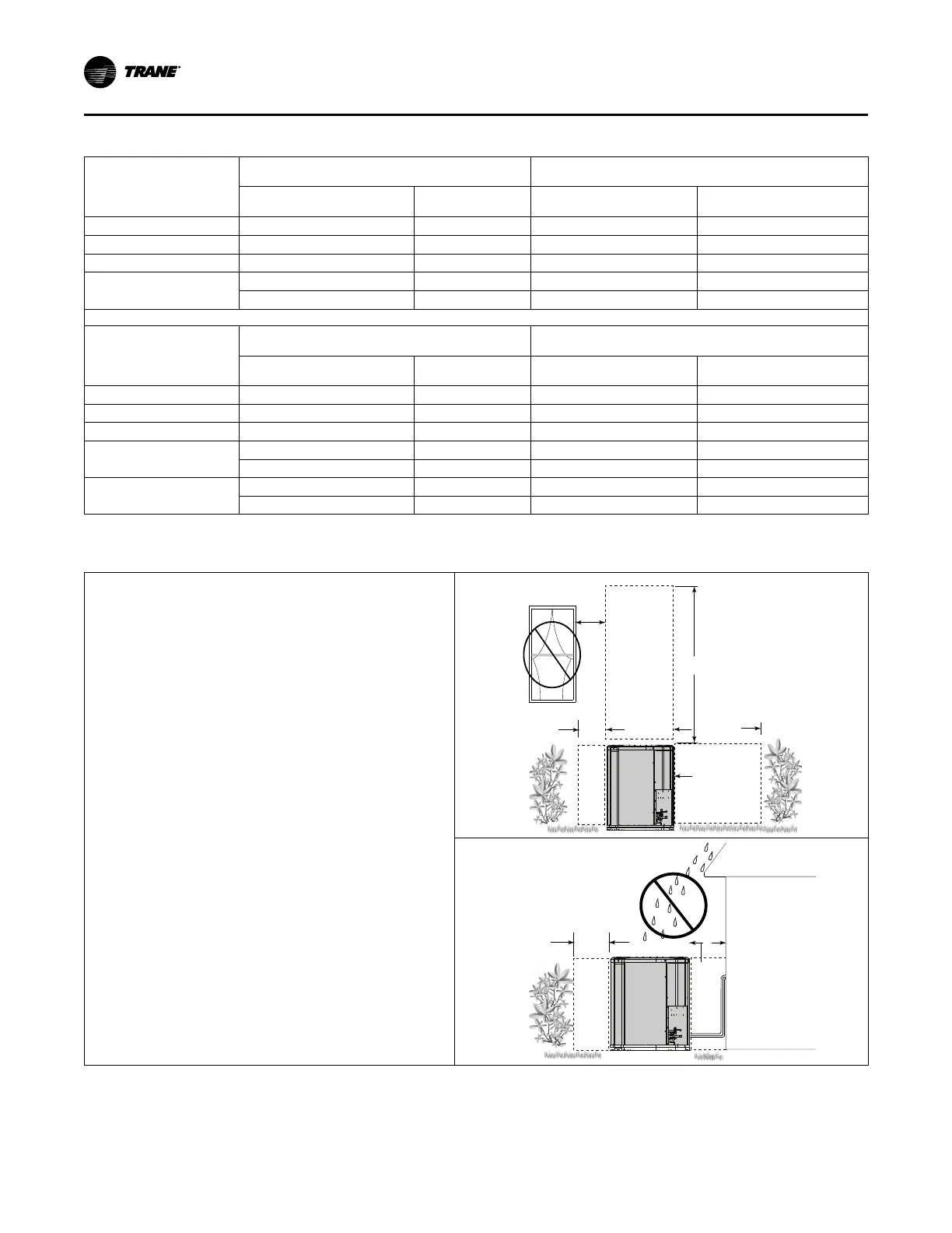
Table 5. Suggested Locations for Best Reliability
• Ensure the top discharge area is unrestricted for at least 5
feet above the unit.
• Provide at least 3 feet clearance in front of the control box
(access panels) and any other side requiring service.
• Do not locate close to bedrooms as operational sounds may
be objectionable.
• Avoid locations near windows and similar areas where
condensation and freezing defrost vapor can annoy a
customer.
• Position the outdoor unit a minimum of 12” from any wall or
surrounding shrubbery to ensure adequate airflow.
• Outdoor unit location must be far enough away from any
structure to prevent excess roof runoff water or icicles from
falling directly on the unit.
• Position the outdoor unit a minimum of 12” from any wall or
surrounding shrubbery to ensure adequate airflow.
• Outdoor unit location must be far enough away from any
structure to prevent excess roof runoff water or icicles from
falling directly on the unit.
Min. 12” to
Shrubbery
Avoid Install
Near Bedrooms
Min 5’ Unrestricted
Access Panel
Min 3’
Unrestricted
Min. 12” to
Shrubbery
Min. 12”
to Wall
UUnniitt LLooccaattiioonn CCoonnssiiddeerraattiioonnss
 Loading...