Installation: Mechanical
Consult a qualified watertreatment specialist to determine whether treatment is need-
ed. The following disclamatory label is provided on each CVGF unit:
The use of improperly treated or untreated water in this equipment may result in scal-
ing, erosion, corrosion, algae, or slime. The services of a qualified water-treatment
specialist should be engaged to determine
what treatment, if any, is advisable. The Trane Company warranty specifically excludes
liability for corrosion, erosion, or deterioration of Trane equipment. Trane assumes
no responsibility for the results of the use of untreated, improperly treated, saline, or
brackish water.
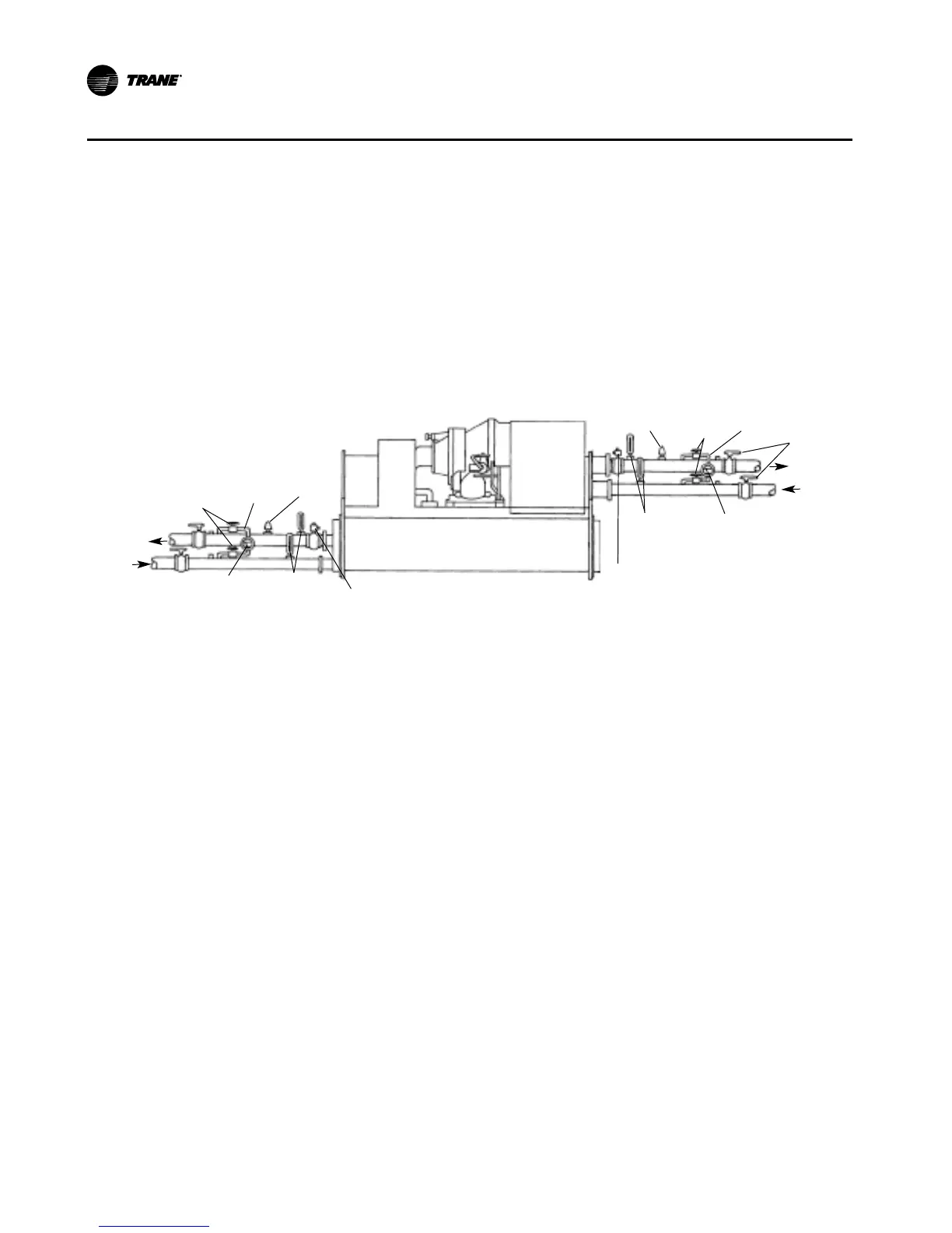
Figure 24. Typical thermometer, valving, and manifold pressure gauge set-up
water flow
Pressure
differential
gauge
Thermometers
Shutoff
valves
Manifold
Flow switch
Isolation
valves
Water Pressure Gauges and Thermometers
Install field-supplied thermometers and pressure gauges (with manifolds whenever
practical) as shown in
Figure 24. Locate pressure gauges or taps in a straight run of pipe; avoid placement
near elbows, and so forth. Be sure to install the gauges at the same elevation on each
shell if the shells have opposite-end water connections.
To read manifolded water pressure gauges, open one valve and close the other (de-
pending upon the reading desired). This eliminates errors resulting from differently
calibrated gauges installed at unmatched elevations.
Water Pressure-Relief Valves
CAUTION
Shell Damage!
Install a pressure-relief valve in both the evaporator and condenser water systems.
Failure to do so could result in shell damage.
Install a water pressure-relief valve in one of the condenser, and one of the evapora-
tor, water box drain connections, or on the shell side of any shutoff valve.
Water vessels with closecoupled shutoff valves have a high potential for hydrostatic
pressure buildup during a water temperature increase. Refer to applicable codes for
pressurerelief valve installation guidelines.
Flow-Sensing Devices
Use field provided flow switches or differential pressure switches with pump interlocks
CVGF-SVX03B-EN
72