AFDH-SVN01A-EN 53
Installation
Note: These power connections should be re-torqued to 44 foot-pounds after the first three to six
months of operation and then on an annual basis thereafter.
4. Put the transition cover back in place and reseal it when finished.
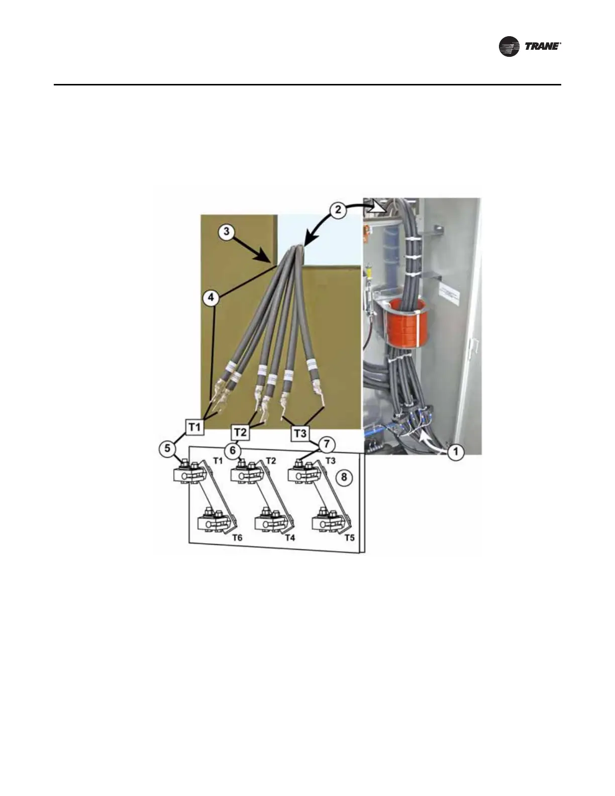
1. Output motor leads coming in from the right hand cabinet compartment (drive module) and
routed up through the CT’s to the motor terminal access cutout
2. Motor leads routed through cabinet motor terminal access cutout
3. Transition cover removed and Z bracket blanked out of photo for clarity
4. Factory installed motor leads are long enough to extend approximately 18-inches out from the
access cutout
5. Attach both T1 motor leads to compressor motor terminal T1
6. Attach both T2 motor leads to compressor motor terminal T2
7. Attach both T3 motor leads to compressor motor terminal T3
8. Compressor motor terminal board
Figure 29. Output wiring from AFDH to CTV motor

 Loading...


