1. Using the supplied harness connect PPF87 to the
2. Route harness to fresh air options module located in
3. After installation is complete, Symbio™ 700 UC unit
installed option.
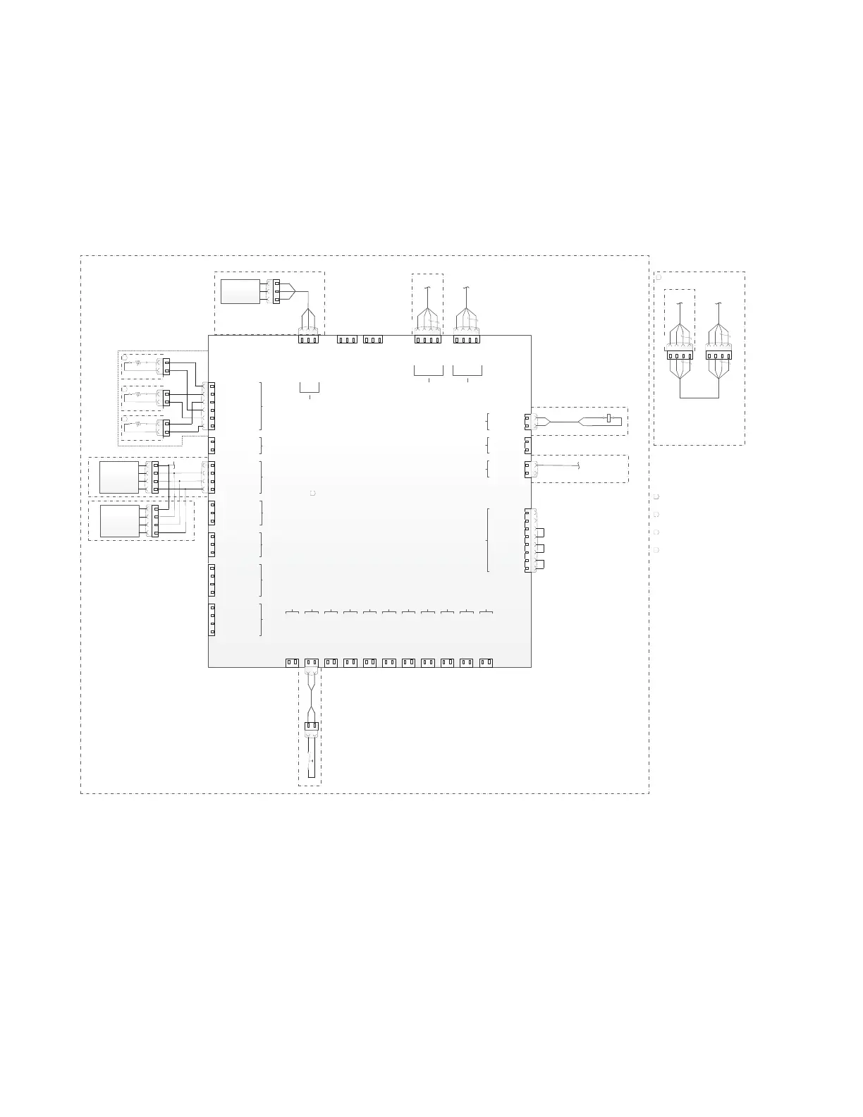
Figure 9. Fresh air options module
R
BL
O
R
P
BL
BK
R
BL
BK
R
BL
O
BK R BL
FRESH AIR OPTIONS MODULE
(FOM)
24 VAC OUT
Spare Universal IO 2
Spare Transducer Zeroing Pin
Common
P13
24 VDC OUT
OA Damper Feedback
OA Damper OUT
Common
P10
24 VDC OUT
Spare Universal IO 1
Spare Transducer Zeroing Pin
Common
P12
Return Air Humidity Input
Common
24 VDC OUT
24 VDC OUT
P9
Outdoor Air Humidity Input
Return Air Temp Input
Spare Binary Output 1
Common
P6
Spare Binary Output 2
Common
P7
Spare Binary Output 3
Common
P8
P2
24 VAC OUT
RA Smoke Detector Input
Common
P1
P4
GND
Address 3
GND
Address 1
GND
Address 2
Address 4
GND
J11
Spare Universal Input 5
Common
P14
Clogged Filter Switch IN
24 VAC OUT
P15
Spare Binary Input 3
P16
Spare Binary Input 4
P17
Spare Binary Input 5
P18
Spare Analog Output 4
Common
Spare Analog Output 3
Common
P21
Spare Binary Output 4
P20
24 VDC OUT
Spare Universal Input 7
Spare Universal Input 6
J4
Spare Analog Output 2
Common
J5P19 J6
3
P11
1
2
1
2
J2
3
1
2
J1
1
2
3
4
1
2
3
4
1
2
1
2
3
4
3
4
1
2
1
2
1
2
1
2
1
2
1
2
1
2
1
2
1
2
1
2
1
2
1
2
1
2
3
4
3
4
5
6
5
6
1
2
1
2
1
2
1
2
1
2
3
4
3
4
5
6
5
6
7
8
7
8
Modbus +
Modbus -
Common
1
23
1
23
1
23
P3
Modbus +
Modbus -
Common
1
23
24 VAC OUT
Common
IMC +
IMC -
1
23
4
IMC Bus
(White)
P5
White
BK R BL O
24 VAC OUT
Common
IMC +
IMC -
1
234
TO UC-P4
SHEET 3
1
23
4
Common
Spare Universal IO 1 (Alt)
5 VDC OUT
Common
5 VDC OUT
Spare Universal IO 2 (Alt)
Spare Binary Input 2
24 VAC OUT
24 VAC OUT
24 VAC OUT
24 VAC OUT
Common
Supply Voltage IN
3
1
2
(Black)
ECA
24 V? IN
DAMPER POSITION IN
DAMPER POSITION OUT
IMC Bus
(White)
(Red)
(Gray)
(Blue)
(White)
(White)
(Black)
(White)
(Purple)
(White) (Mint) (Red) (Pink) (Orange) (Green) (Green) (Green) (Blue) (Yellow)
(Black)
(Black)
(Green)
(Brown)
3
1
2
3
1
2
RASD
24 VAC IN
Smoke Detector OUT
3
1
2
Common
CFS
BK R
BK R
1
2
1
2
1
2
1
1
Common
4 4
BK
O
1
2
1
2
Oponal Return Air Humidity Sensor
-H°
RAH
3
R
Y
1
2
1
2
Oponal Outdoor Air Humidity Sensor
-H°
OAH
4
t°
RAT
BL
BR
1
2
1
2
Oponal Return Air Temp Sensor
2
FRESH AIR OPTIONS MODULE ONLY PRESENT ON CERTAIN UNIT CONFIGURATIONS. SEE INSET A FOR
UNITS WITHOUT FRESH AIR OPTIONS MODULE.
1
BK R BL O
BK R BL O
White
BK R BL O
1
234
1
23
4
White
BK R BL O
1
234
TO IOM-P4
SHEET 5
1
23
4
TO AIRFI
1
INSET A
BK R
BK R
XFR
2
1
White
BK R BL O
1
234
TO AIRFI
3
4
2
RETURN AIR TEMP SENSOR PRESENT ON UNITS WITH DIFFERENTIAL DRY BULB, REFERENCE ENTHALPY,
AND COMPARATIVE ENTHALPY CONTROL
RETURN AIR HUMIDITY SENSOR PRESENT ON UNITS WIT H REFERENCE ENTHALPY AND COMPARATIVE
ENTHALPY CONTROL
RETURN AIR HUMIDITY SENSOR PRESENT ON UNITS WITH COMPARATIVE ENTHALPY CONTROL
PPF62
PPF63
PPF64
PPF87PPM87
PPF88PPM88
PPF86
PPM86
BK
2
1
TO LINE 320
Sheet 6
J11-1
TO LINE 322
Sheet 6
J8-1
3
1
2
ECA
24 V? IN
DAMPER POSITION IN
DAMPER POSITION OUT
Common
4
BK
R
BL
O
3
1
2
4
Oponal Horizontal Low Leak
Oponal Economizer
Oponal Economizer
Oponal Return Air Smoke Detector
Oponal Power Exhaust
 Loading...