70 RLC-SVD03A-EN
Module Power and Miscellaneous I/O
I/0 terminals
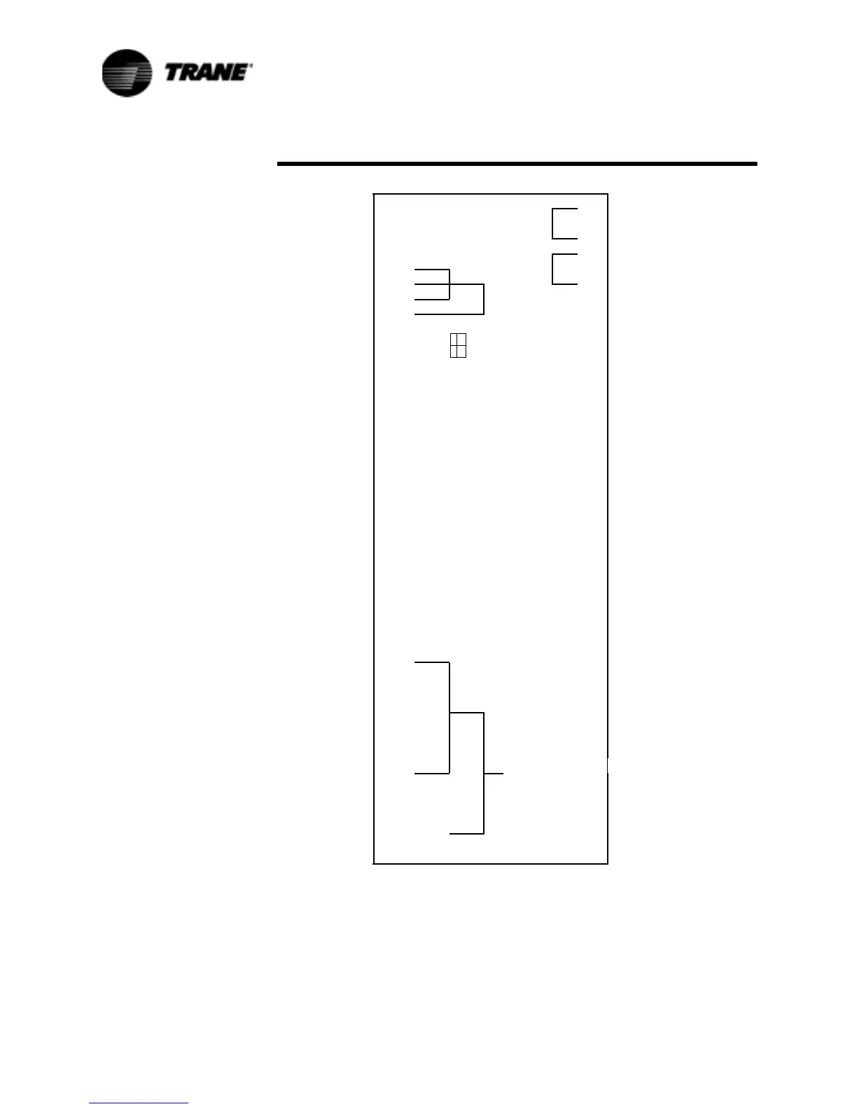
For the checkout of the I/O, refer to the block diagram of the EXV module in
Table 21 and the Chiller Wiring Diagrams for both high and low voltage
circuits. All voltages are measured differently between terminal pairs
SEHI Valve Module
° TP1 +5V J6-1 — 115VAC HOT
J6-2 — 115VAC HOT
J6-3 — KEY (N/C)
J6-4 — NEUTRAL
IPC (+) — J1-4 J6-5 — NEUTRAL
IPC (-) — J1-3
IPC (+) — J1-2
IPC (-) — J1-1
MANUF. NO CONN. — J2-2
USE ONLY NO CONN. — J2-1
L H
0
LOW PRESSURE SIG.— J7-5
I
W
SWITCH CIRCUIT 1 GND — J7-4
G
KEY — J7-3
H
V
LOW PRESSURE SIG. — J7-2
0
SWITCH CIRCUIT 2 GND — J7-1
V
L 0
T
SATURATED EVAPORATOR — J3-9
L
A
TEMPERATURE CIRCUIT 1 — J3-8
T
T A
A
COMPRESSOR SUCTION — J3-7
G
G
TEMPERATURE CIRCUIT 1 — J3-6
E
E
N/C KEYING — J3-5
SATURATED EVAPORATOR — J3-4
I
I
TEMPERATURE CIRCUIT 2 — J3-3
N
N P
P
COMPRESSOR SUCTION — J3-2
U
U
TEMPERATURE CIRCUIT 2 — J3-1
T
T S
S
ELECTRONIC
EXPANSION
VALVE
CIRCUIT 1
RED — J4-5
.
GREEN — J4-4
O
KEY (N/C) — J4-3
J4-2
U
WHITE —
T
BLACK — J4-1
P
U
ELECTRONIC
EXPANSION
VALVE
CIRCUIT 2
RED — J5-6 24 VDC Peak only
when the Phase is
being stepped.
T
GREEN — J5-5
S
KEY (N/C) — J5-4
KEY (N/C) — J5-3
WHITE — J5-2
BLACK — J5-1
Figure 21 SEHI Electronic Expansion Valve Module (1U3)
off
on
SW-1
 Loading...


