12 18-HD68D1-3
The manufacturer has a policy of continuous product and product data improvement
and it reserves the right to change design and specifications without notice.
Representative-only illustrations included in this document.
6200 Troup Highway
Tyler, TX 75707
© 2011 Trane
Section 7. Troubleshooting
Troubleshooting
Symptom Possible Cause Action
COMM LED is not
flashing the ap-
propriate number
of devices
Loss of 24VAC between power (R) and common (B) Check for proper incoming 24VAC power
One or more communicating devices is not com-
municating
• ~12VDC between D & B = Proper communication
• ~16VDC between D & B = Loss of communication
• Less than ~12VDC between D & B = shorted or no power
Check for open or shorts in field wiring
Evaluate other communicating devices and use
the service facts of that device if not communi-
cating properly
Bit Master LED is
off or fluttering
Loss of 24VAC between power (R) and common (B) Check for proper incoming 24VAC power
Loss of communication
• 0VDC between D & B (shorted or no power)
• Less than ~12VDC between D & B (low level short)
Check for shorted wire between data (D) and
common (B) wires
HVAC System
LED is not illumi-
nating when Relay
Panel is calling for
a particular relay
Control is not calling
Check the System Report screen at the control
to verify demand
Relay Panel failed
Verify 24VAC between relay output terminal and
common (B)
**Relay output contains snubber circuits; always
check with a load applied
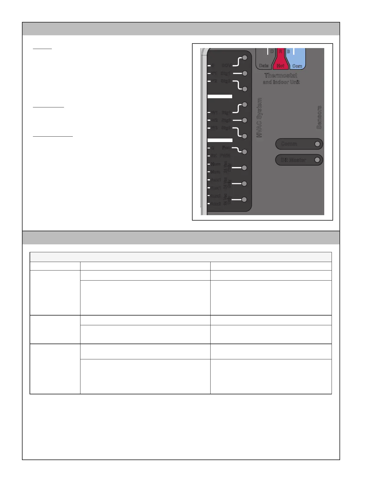
Section 6. LED Indicators
Aux2
Bit Master
Comm
HVAC System
Sensors
Thermostat
and Indoor Unit
Data
Hot
Com
D R
B
24 Vac
Only
24 Vac
Only
24 Vac
Only
Aux2
Aux1
Aux1
Hum
Hum
BK
PWM
Fan
G
W3 Stg3
W2 Stg2
W1 Stg1
Y1 Stg1
Y2 Stg2
0 SOV
Comm
Communication LED – Amber
• LED on when first powering up
• LED flashes number of communicating com-
ponents in the system.
• (ex. communicating control with relay panel
will equal two flashes)
Bit Master
Bitmaster/Clock Signal LED – Green
• LED on when Clock is working
HVAC System
HVAC System LEDs – Green
• A Green LED will illuminate when the relay is
energized.