18-HD68D1-3 3
Unit Location Considerations
The unit’s rugged design allows installation in closet, attic or other non-condensing locations free from obstruc-
tions or other hazards.
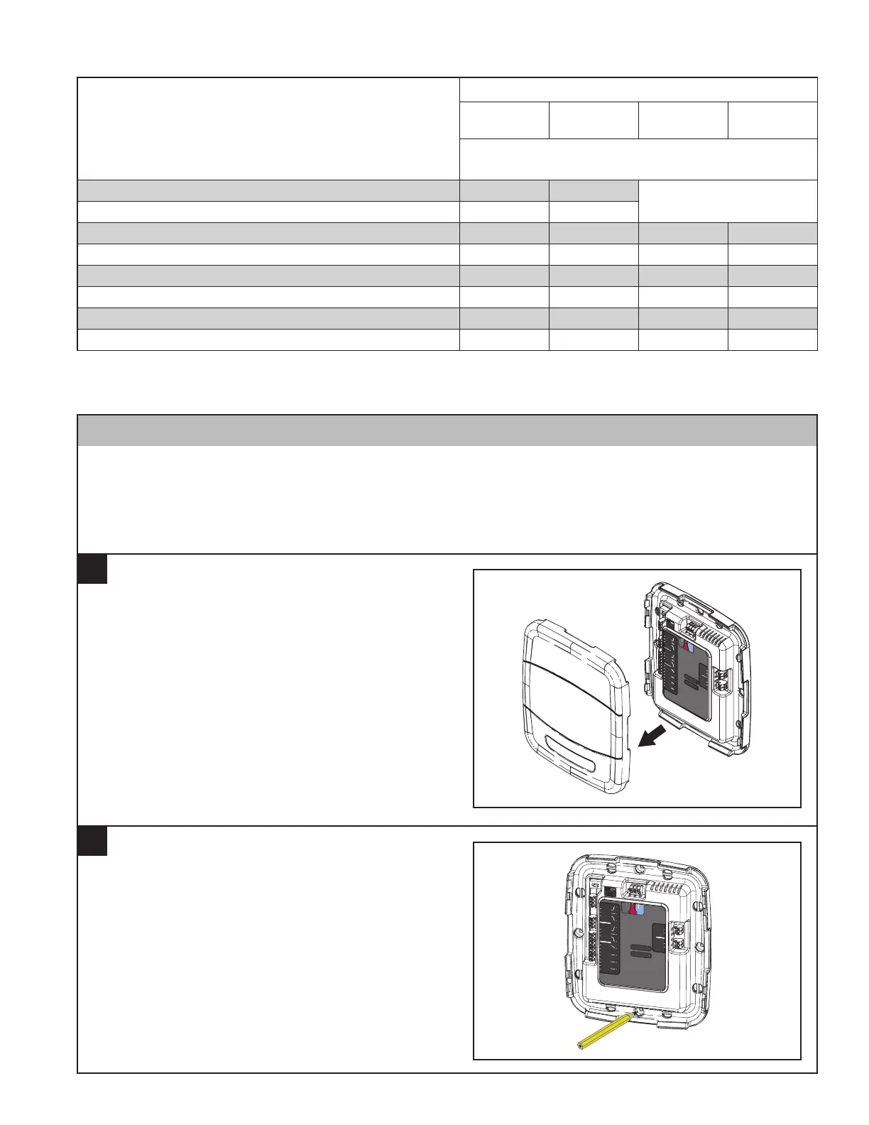
Remove cover by grasping at edges and gently
pulling the cover straight towards you. It should
release without much effort.
Aux2
Relay Panel
Bit Master
Comm
HVAC System
Sensors
Thermostat
and Indoor Unit
Outdoor
Remote
Data
Hot
Com
D R
B
Indoor
RS
RS
ODT
ODT
24 Vac
Only
24 Vac
Only
24 Vac
Only
Aux2
Aux1
Aux1
Hum
Hum
BK
PWM
Fan
G
W3 Stg3
W2 Stg2
W1 Stg1
Y1 Stg1
Y2 Stg2
0 SOV
NORM
Dual Fuel
Switch
DUAL
Aux2
Relay Panel
Bitmaster
Comm
HVAC System
Sensors
Thermostat
and Indoor Unit
Outdoor
Remote
Data
Hot
Com
D R
B
Indoor
RS
RS
ODT
ODT
24 Vac
Only
24 Vac
Only
24 Vac
Only
Aux2
Aux1
Aux1
Hum
Hum
BK
PWM
Fan
G
W3 Stg3
W2 Stg2
W1 Stg1
Y1 Stg1
Y2 Stg2
0 SOV
NORM
Dual Fuel
Switch
DUAL
Relay Panel
Section 3. Installation
Remove Cover
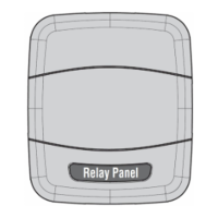
Mark Mounting Location
1
2
Mark four holes on the wall using the base as a
template. A level may be used to ensure accuracy.
Indoor Unit Type
Comm
Furnace
Comm
Air Handler
24V
Furnace
24V
Air Handler
OD Unit Type
Minimum Indoor 24V Control Power
Transformer Size, VA*
Communicating Heat Pump 35 35
See Below
Communicating Air Conditioner 35 35
24Volt-Controlled Single Stage Heat Pump 35 40 35 40
24Volt-Controlled Single Stage Air Conditioner 35 40 35 40
24Volt-Controlled 2-Stage Single Compressor Heat Pump 65 75 65 75
24Volt-Controlled 2-Stage Single Compressor Air Conditioner 50 40 50 40
24Volt-Controlled 2-Stage Dual Compressor Heat Pump 50 75 50 75
24Volt-Controlled 2-Stage Dual Compressor Air Conditioner 35 40 35 40
*Note: The VA rating of all 24V field-installed accessories must be added to the above for sizing indoor unit control transformers or the accessories
must be powered separately.
2.5 System Transformer Sizing Guidelines