18-HD68D1-3 5
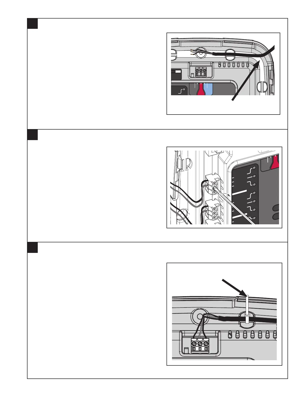
Using 1/8” blade screwdriver, attach all wires se-
curely to the proper terminals on the Relay Panel.
Refer to the following section for detailed terminal
information.
(See the Field Wiring Diagrams section for com-
mon system configurations.)
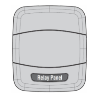
Secure all wires with the supplied wire ties to en-
sure that wires are kept in place and not strained.
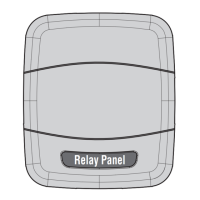
Run wires within the recessed wire “raceway”. Be
sure there is ample length to reach the connectors.
Bi
HVAC System
Thermo
and Indo
Data
Hot
D R
M
Fan
G
W3 Stg3
W2 Stg2
W1 Stg1
Y1 Stg1
Y2 Stg2
0 SOV
Aux2
Relay Panel
Fault
Comm
Bit Master
HVAC System
Sensors
Thermostat
Outdoor
Remote
Data
Hot
Com
DR
B
Indoor
RS
RS
ODT
ODT
24 Vac
Only
24 Vac
Only
24 Vac
Only
Aux2
Aux1
Aux1
Hum
Hum
BK
PWM
Fan
G
W3 Stg3
W2 Stg2
W1 Stg1
Y1 Stg1
Y2 Stg2
0 SOV
NORM
Dual Fuel
Switch
DUAL
Aux2
Relay Panel
Fault
Comm
Bit Master
HVAC System
Sensors
Thermostat
Outdoor
Remote
Data
Hot
Com
DR
B
Indoor
RS
RS
ODT
ODT
24 Vac
Only
24 Vac
Only
24 Vac
Only
Aux2
Aux1
Aux1
Hum
Hum
BK
PWM
Fan
G
W3 Stg3
W2 Stg2
W1 Stg1
Y1 Stg1
Y2 Stg2
0 SOV
NORM
Dual Fuel
Switch
DUAL
Route wires into “Raceways”
Secure wires with Wire Ties
Attaching Wires
Securing Wires
Routing Wires
6
7
5