28
18-HD82D1-1B-EN
XR724 INSTALLER’S GUIDE
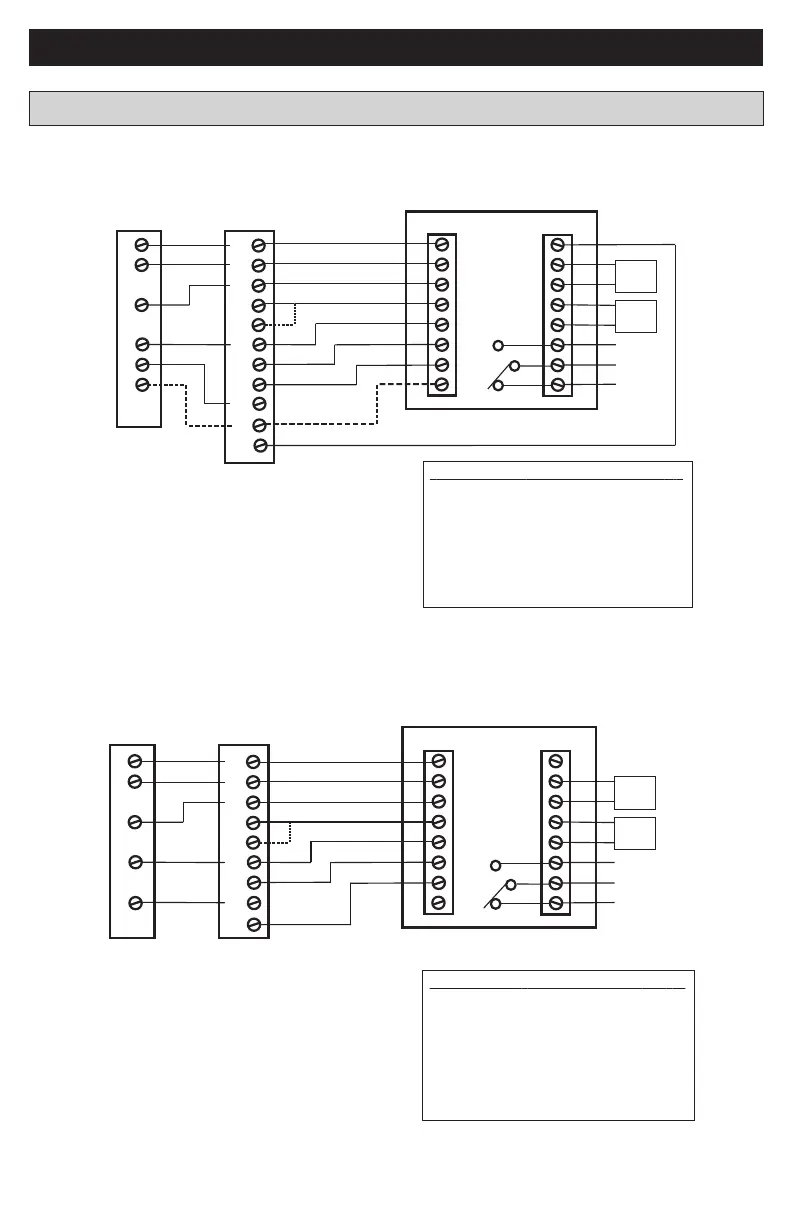
Heat Pump Diagram 1: 1 or 2 Stage Heat Pump w/TAM7 Model Variable Speed Air Handler
G
W1
YI (In)
R
B/C
Y2
BK
W2
Y1
R
B
Y2
Notes:
1. Cut/remove the factory installed “BK” jumper
at the indoor unit
2. Jumper “W2” to “W3” if three stages of indoor heat
are available
3. “YI” and “YO” connections must be made as show
for freeze protection and internally mounted
condensate overflow circuits to work properly
4. If 3rd party condensate overflow switches are
installed, they should be wired between “Y1” of the
thermostat and “YI” of the airflow control board
Sensor Options in the Installer Settings/Sensor Settings menu
Remote Sensor (connect to the RS terminals)
- None
- Replaces internal sensor
- Average with internal sensor
Outdoor Temp Sensor (connect to the ODT terminals)
- None
- Outdoor
Caution: Do not run sensor wires in the same bundle with HVAC
wires. Keep away from high voltage wiring to avoid interference.
Remote Temperature Sensor Connections and Operation:
Aux relay
outputs
RS
C
RS
R
ODT
W1
W2
BK
ODT
NO
C
Y1
NC
Y2
O/B
G
Thermostat Connection
Outdoor
Sensor
Remote
Sensor
O
W3
X2
O
YO
Variable Speed Air
Handler & Electric Heat
One or Two stage
Heat Pump
(Note 2)
(Note 3)
(Note 4)
(Note 1)
Variable Speed Air
Handler & Electric Heat
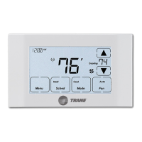
Heat Pump Diagram 2: 1 Stage Heat Pump w/GAM5A & TAM4 Model Air Handler
G
W1
YO
R
B/C
YI
W2
One stage
Heat Pump
Y
R
B
Notes:
1. Jumper “W2” to “W3” if three stages of indoor heat
are available
2. “YI” and “YO” connections must be made as shown
for freeze protection and internally mounted conden-
sate overflow circuits to work properly.
3. If 3rd party condensate overflow switches are
installed, they should be wired between “Y” of the
thermostat and “YI” of the airflow control board.
Sensor Options in the Installer Settings/Sensor Settings menu
Remote Sensor (connect to the RS terminals)
- None
- Replaces internal sensor
- Average with internal sensor
Outdoor Temp Sensor (connect to the ODT terminals)
- None
- Outdoor
Caution: Do not run sensor wires in the same bundle with HVAC
wires. Keep away from high voltage wiring to avoid interference.
Remote Temperature Sensor Connections and Operation:
Aux relay
outputs
RS
C
RS
R
ODT
W1
W2
BK
ODT
NO
C
Y1
NC
Y2
O/B
G
Thermostat Connection
Outdoor
Sensor
Remote
Sensor
O
W3
X2
O
(Note 1)
(Note 2)
(Note 3)
Heat Pump Wiring Diagrams