35
18-HD82D1-1B-EN
Variable Speed
Oil Furnace
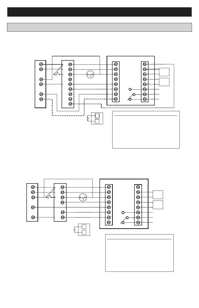
Dual Fuel Diagram 3: 1 or 2 Stage Heat Pump w/Variable Speed Oil Furnace
G
W1
Y1
R
B/C
Y2
BK
W2
One or Two Stage
Heat Pump
Y 1
R
B
Y2
Notes:
1. Cut/remove the factory installed “BK” jumper at the indoor unit
2. BT (Bonnet Thermostat) model THT1248 required for
dual fuel, oil furnace applications
3. For non-Trane/American Standard indoor units “BK” is not
connected and “Y1”/”Y2” must be connect at indoor unit
4. Field supplied relay (R1) required for oil burner primary
Sensor Options in the Installer Settings/Sensor Settings menu
Remote Sensor (connect to the RS terminals)
- None
- Replaces internal sensor
- Average with internal sensor
Outdoor Temp Sensor (connect to the ODT terminals)
- None
- Outdoor
Caution: Do not run sensor wires in the same bundle with HVAC
wires. Keep away from high voltage wiring to avoid interference.
Remote Temperature Sensor Connections and Operation:
BT
Aux relay
outputs
RS
C
RS
R
ODT
W1
W2
BK
ODT
NO
C
Y1
NC
Y2
O/B
G
Thermostat Connection
Outdoor
Sensor
Remote
Sensor
O
X2
O
T
T
R1
Oil Burner Primary
R1
(Note 2)
(Note 1)
(Note 3)
(Note 4)
(Note 4)
Non-Variable Speed
Oil Furnace
Dual Fuel Diagram 4 : 1 Stage Heat Pump w/non-Variable Speed Oil Furnace
G
W1
Y
R
B/C
W2
Single Stage
Heat Pump
Y
R
B
Notes:
1. BT (Bonnet Thermostat) model THT1248
required for dual fuel, oil furnace applications
2. Field supplied relay (R1) required for oil burner primary
Sensor Options in the Installer Settings/Sensor Settings menu
Remote Sensor (connect to the RS terminals)
- None
- Replaces internal sensor
- Average with internal sensor
Outdoor Temp Sensor (connect to the ODT terminals)
- None
- Outdoor
Caution: Do not run sensor wires in the same bundle with HVAC
wires. Keep away from high voltage wiring to avoid interference.
Remote Temperature Sensor Connections and Operation:
BT
Aux relay
outputs
RS
C
RS
R
ODT
W1
W2
BK
ODT
NO
C
Y1
NC
Y2
O/B
G
Thermostat Connection
Outdoor
Sensor
Remote
Sensor
X2
O
T
T
R1
Oil Burner Primary
R1
(Note 1)
(Note 2)
(Note 2)
Dual Fuel Wiring Diagrams
XR724 INSTALLER’S GUIDE
 Loading...